
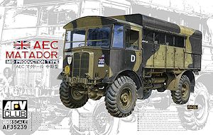
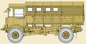
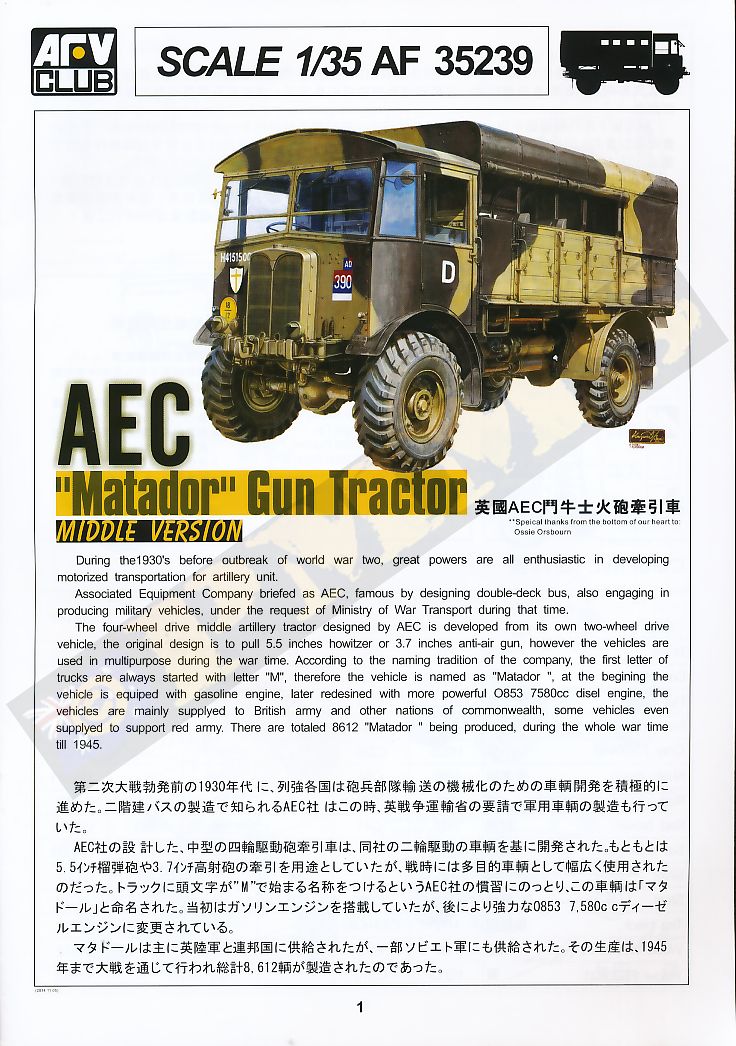
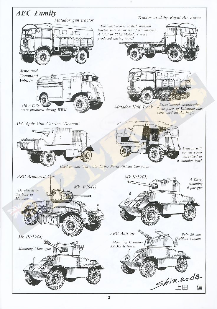
AEC "Matador" Mid Production Type
AFV Club 1:35 Kit No. AF 35239
Review by Terry Ashley
Prior to outbreak of WWII, the British Army was planning a wheel armoured commander vehicle to provide the armoured troop commander and staff an appropriate command post.
CS9/LAC 4x4 chassis from Morris and Guy Lizard 4x4 chassis were adopted from 1937 to 1939, and 36 armoured commander vehicles completed. Those vehicles were used in inland UK. A few Guy Lizard armoured commander vehicles were sent to North Africa, saw services with the 8th Army. At the same time armoured regiments were blooming, obviously more armoured commander vehicles were needed.
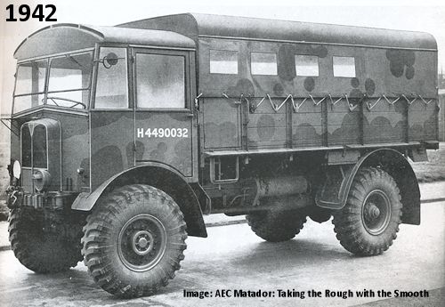
Associated Equipment Company (AEC), who was best known by London double deck buses, was awarded with a contract from the Ministry of War Transport in April 1940, to produce a Matador 4x4 artillery tractor and an armoured commander vehicle with Matador 4x4 chassis. By 1941, AEC devoted itself to military needs totally, and the armoured commander vehicle entered mass production. With armours up 10-12 mm thick and weight up to 12.2 tons, the vehicle was able to accommodate up to 7-8 personnel. High Power and Low Power versions were built, with different radio equipment. A total of 415 were produced. It was nicknamed Dorchester by the troops, after the luxury hotel in London because it is very comfortable. The AEC Armoured Command Vehicle firstly saw service in North Africa Campaigns in the British Army service and throughout the war. 7 vehicles were handed to the Australian troops.
The kit can be built in distinct sub-assemblies, the chassis/suspension, the front cab and the large body tray which allows work on one while the glue dries on another, there are also numerous smaller sub-assemblies incorporated into these and planning ahead to assemble these smaller assemblies will also make final assembly easier.
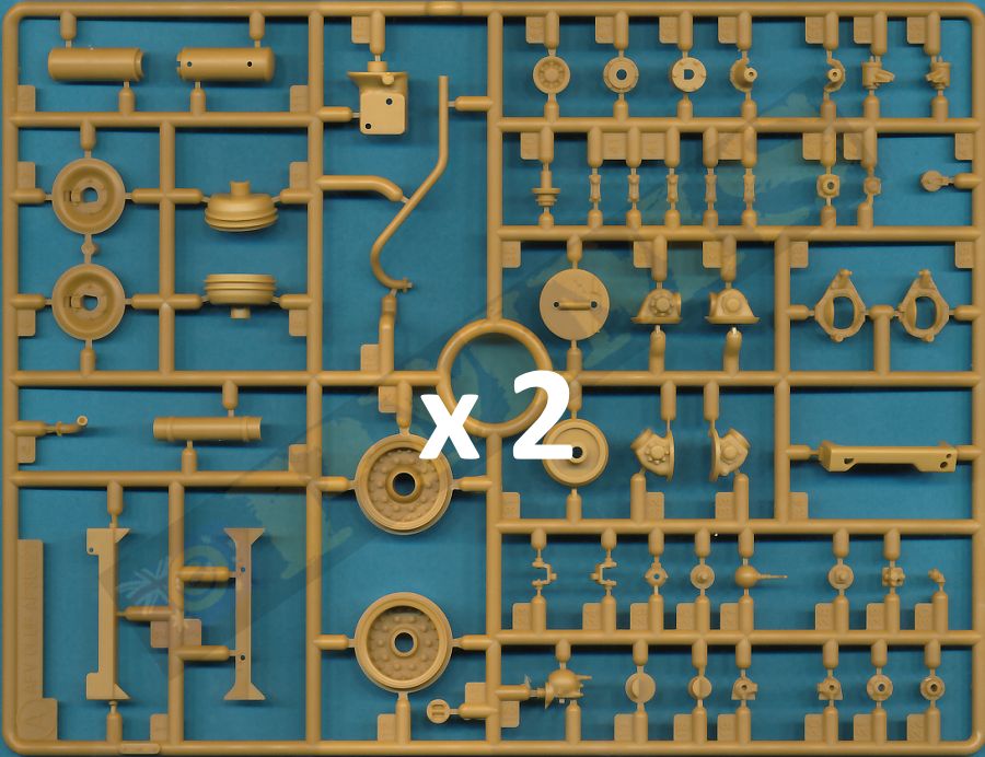
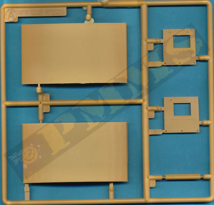
The kit again uses the basic chassis and suspension for the Dorchester/early Matador kits so you need to take care when selecting the parts as the original parts are still included. The other thing to watch is due to some sprues being from the Dorchester kit and others new for the Matador kits there are duplicate sprue numbers. i.e. there are three sprue A, two sprue B and two sprue H so you need to take care to find the right part on occasions, especially with the suspension parts.
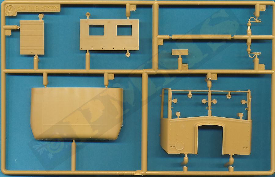
The Early Matador kit (AF 35236) instructions had a number of part numbering errors as indicated in the review of that kit and thankfully all of these have been corrected in this kits instructions, so you can just dive without hitting any such snags.
I don’t have any 1:35 plans of the Matador at this time but available data gives the vehicle dimensions as:
Wheelbase 12ft 7 1/2 in, Overall Length 20ft 9 1/2 in, Width 7ft 10 1/2 in, Height 10ft 2 in which equates in 1:35 scale to; Wheelbase 109.95mm, Length 181.06mm, Width 68.58mm, Height 88.54mm. The built model measures out well to those dimensions give or take an mm here and there but this is only a rough analysis so overall I’d suggest the model is dimensionally accurate in so far as there are no glaring discrepancies.The kit consists of 12 plastic sprues and 1 etched fret with:
- 479 parts in light beige plastic
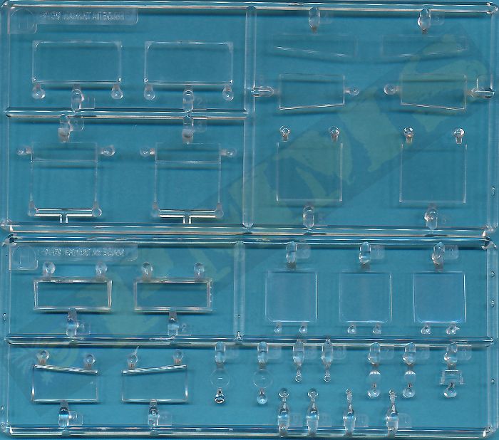
- 28 clear parts
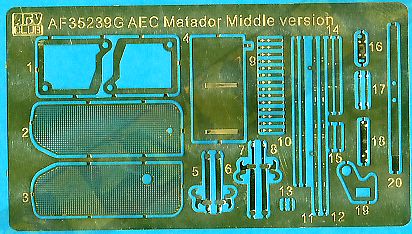
- 38 PE parts
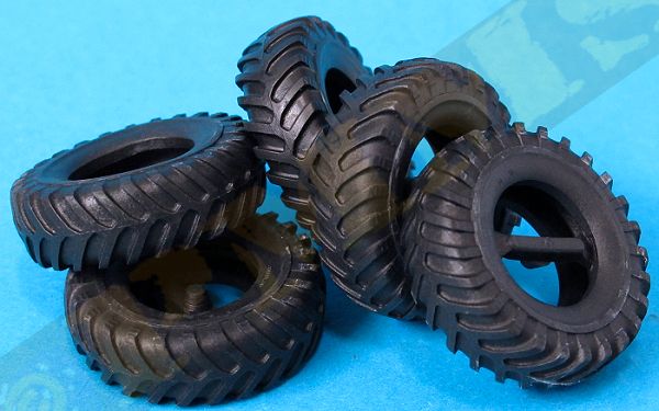
- 5 vinyl tyres
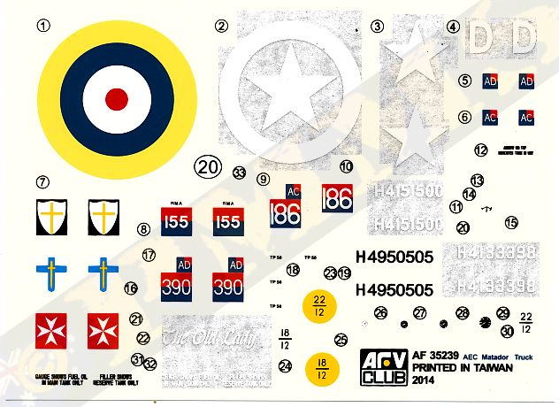
- 1 decal sheet
- 1 sheet clear film windows
- 1 x 16 page instruction booklet
The standard of moulding is extremely high with clean crisp details on the chassis/suspension and body parts as well as the many very small plastic parts that will need care removing from the sprues and during assembly to avoid damage. There is some fine flash on some parts that’s needs attention but the pin marks are kept to a bare minimum through the extensive use of the knock out nodes now common on kits.
As this kit is basically the same as the previous Matador kit the comments below are mostly from the previous kit review with some amendments and additions for the new cab and roof parts as applicable.
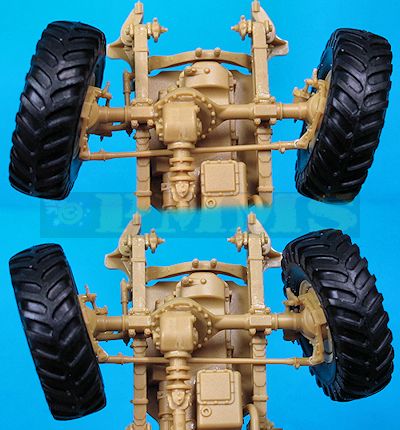
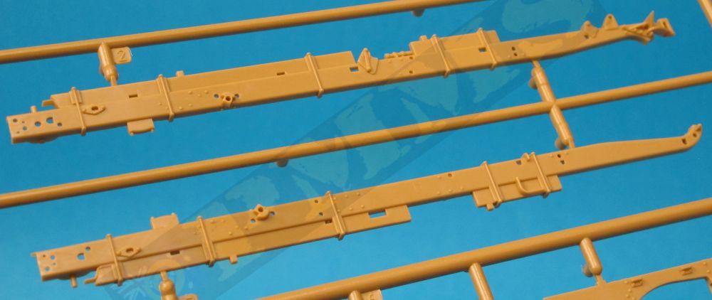
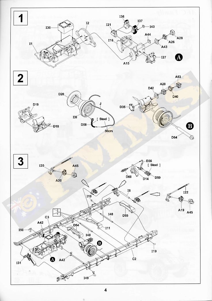
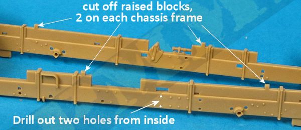
The chassis has the two side U frames separate with numerous cross members (note there are a few chassis frame modifications required before assembly, (see image) along with the engine underside oil pan and gearbox (which is the only engine detail included in the kit) as well as the winch sub-assembly and they all need to be aligned as the two chassis frames are fitted. This is made easier by gluing the various cross members and front engine under pan to one of the chassis frames ensuring they are all fitted perfectly square and level. A point with the winch assembly you should shorten the pin on part A53 to allow this to fit against the transfer case fitted later, or open up the locating hole for this pin in the transfer case.
A couple of things to watch here is the front curved cross member (part I31) has a large pin on the rear side that needs to be removed and there are pin marks along the insides of the chassis frames that can be left as they can’t be seen after assembly and don’t impede assembly. The other chassis frame can be glued in place ensuring the cross members sit snugly in place which wasn’t a problem due to good fit. Added to the inside of the left chassis frame is a small transfer case mounting (part I7) but this is best left off until after the transfer case is added later as it makes fitting the transfer case quite tricky if fitted beforehand.
Other larger items added are the compressed air tank and large fuel tank and these all fitted together very well although the air tank guard is very thin and needs care removing from the sprue and in fitting. There are three winch cable guide rollers added to the rear of the chassis but the outer rollers are hard to fit due to small tabs on the end of the chassis beams and I had to bend these out of the way to fit the rollers and then reposition the tabs, nothing to exciting. There are numerous small delicate items added such as the rear brake cylinders, winch cable guides and with due care these all fit okay.
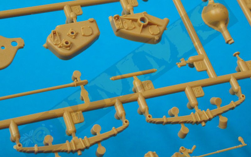
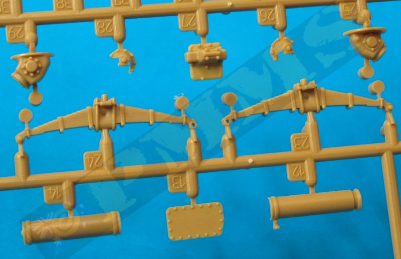
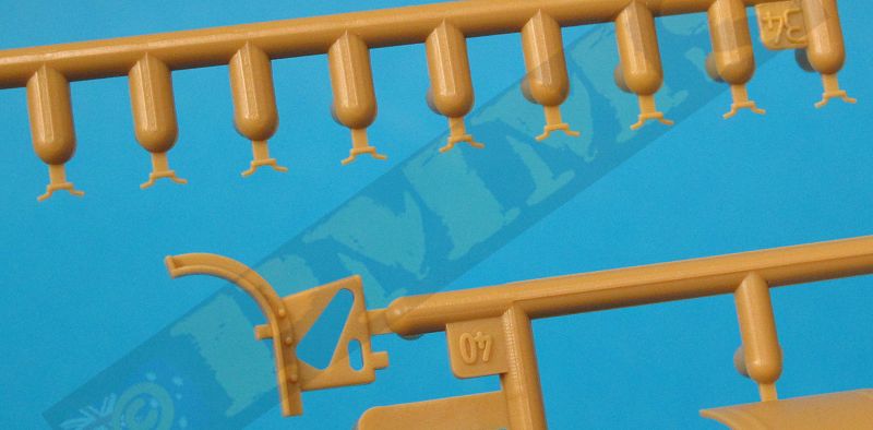
Added to the front and rear of the chassis are the two leaf spring mounted tow hooks fitting into brackets on each chassis frame. Assembly of the spring tow hitches is fairly straightforward but the rear spring has two small mounting brackets fitted to the ends of the chassis frames, each bracket has four mounting pins with the instructions showing to cut off one of these pins before fitting. I found it easier to actually cut off two of the pins leaving just two diagonal pins that correspond to the larger holes in the chassis frames. It’s best to glue one of the brackets (part F33) in place and let the glue dry before fitting the spring and other bracket for easier fitting.
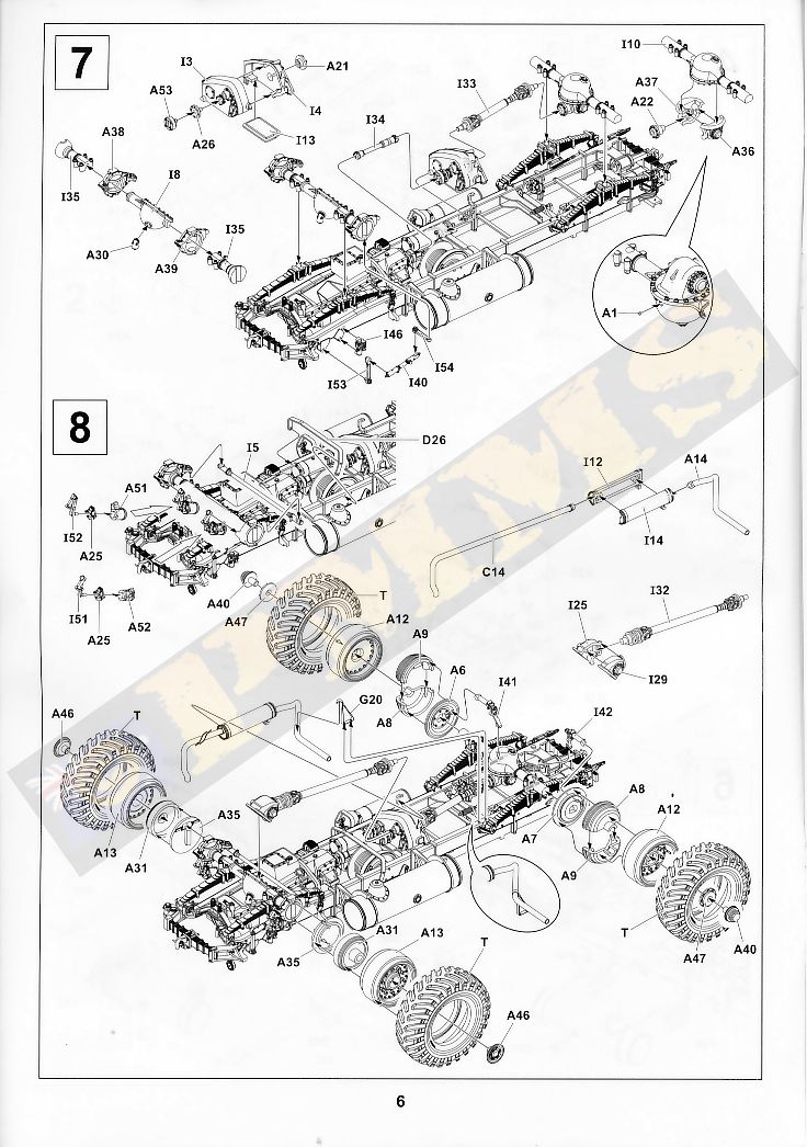
Adding the suspension springs is quite straightforward although care in needed as the spring mountings are all small separate parts but by taking things carefully and noting the different part numbers in the instructions there shouldn’t be any problems? Note the position of the axle locating pins on the front springs, these pins are positioned outwards, if you fit the spring around the wrong way with the pins inwards the axles will not fit properly, this is shown in the instruction so take care to fit these correctly.
Assembly of the large differentials, large transfer case and drive shafts is again straightforward without any fit problems; the front differentials has separate outer sections and make sure the steerable wheel mountings (parts A38, A39) are left unglued at this stage. The 3 part brake cylinders (parts I52/A25/A51 and I51/A25/A52) that attach to the wheel mountings fit okay but the instructions are a little vague on their placement so again make sure these sit right before gluing.
Adding the large transfer case to the centre of the chassis is by way of a mounting lug into cross member D54 and the other end resting on the chassis frame, just make sure this is sitting level with the cross member as the glue dries. The corresponding drive shafts are then fitted into place to the winch and the front and rear differentials without problems although I did have to angle down the front drive shaft a little to mate properly.
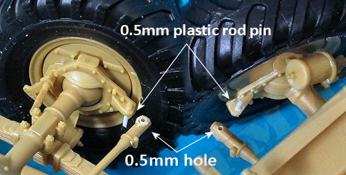
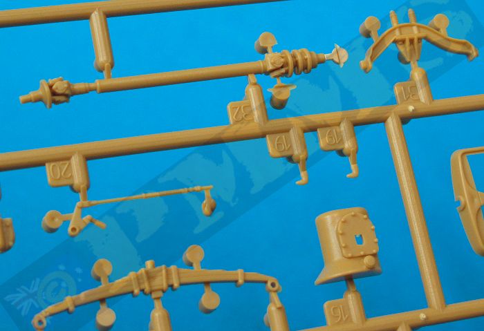
The front wheel mountings are joined by the steering arm rod (part I5) and this allows you to position the wheels at any angle but are not designed to be movable after assembly, to make the wheels steerable is very easy and takes about 5 minutes work. Simply replace the short pin on the wheel mountings with a longer length of plastic rod (I used 0.5mm) and drill a corresponding 0.5mm hole through the end of the steering arm, the steering arm can then be fitted over the pins and you have steerable front wheels. When fitted the suspension springs will hold the steering arm in place so no need to heat melt the end of the plastic pin.
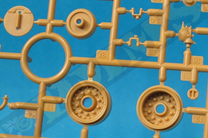
The front wheels have two part brake drums that fit inside the one piece wheel rim which has very nicely done bolt head detail and secured in place with the out wheel hub (part A46). This is glued to the outer brake drum allowing the wheel to rotate if careful with the glue.
The vinyl tyres are cleanly rendered tread and have very fine tyre data’embossed on the sidewalls. The tyres are slipped over the rims and you can fit the tyre before attaching the rims to the axles to make this a little easier if you wish? The assembled wheels are fitted to the wheel mountings (parts A38, A39) and if you want the wheels steerable make sure not to get glue on the axle stubs in the process, this is a fairly easy job as the parts are quite large making handing easier.
The rear wheels are similar with 3 part brake drums and the wheel rims held in place by the outer bolt ring and hub cap (parts A47, A40) and again the rims can rotate if careful with the glue, the assembled wheels just glue to the axle stubs with the inner linkages added (parts I41) for quite robust and detailed suspension assemblies. The four part muffler assembled easily and has a redesigned exhaust pipe making fitting easier than with the first Matador kit.
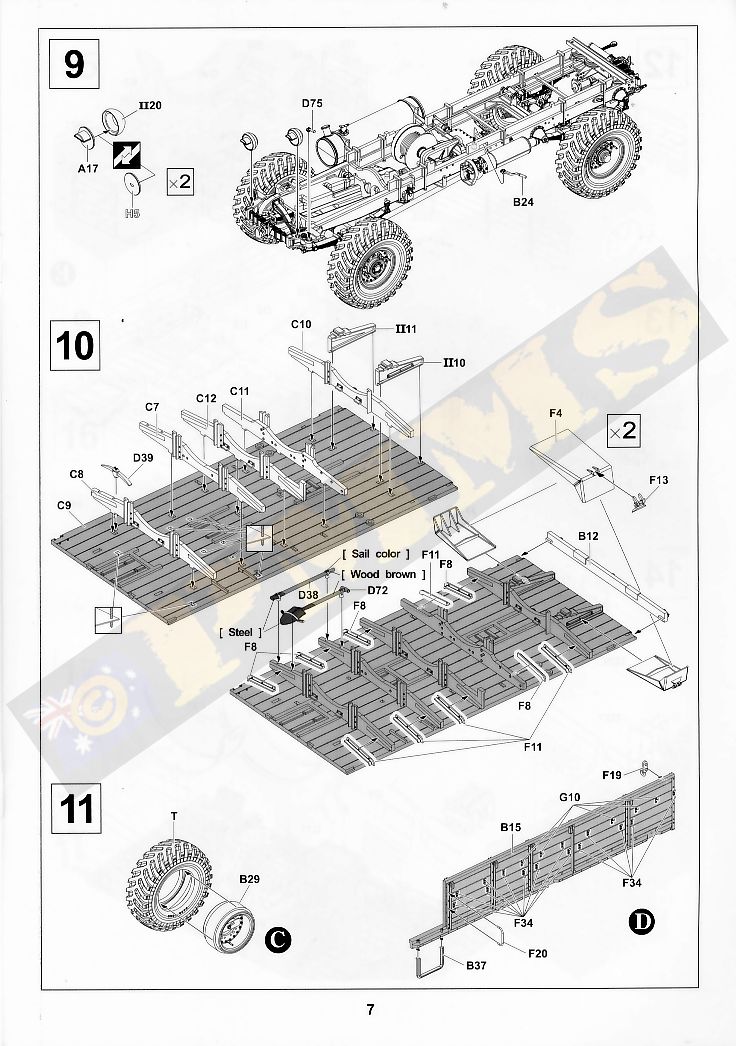
The final items added to the chassis are the front mounted horn and head lights with the option of clear glass or blackout covers, these would be the preferred option for wartime vehicles. When fitting the separate blackout face you need to make sure this is set at right angles to the lower light mounting post as there are no locating tabs for the covers.
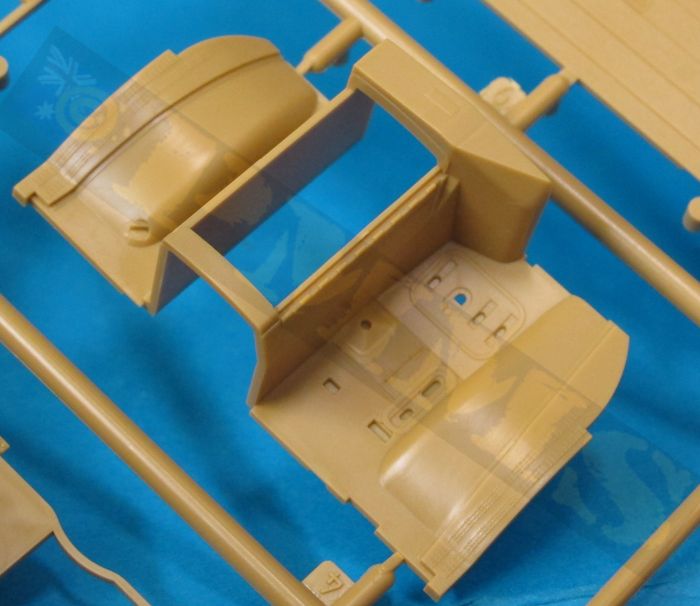
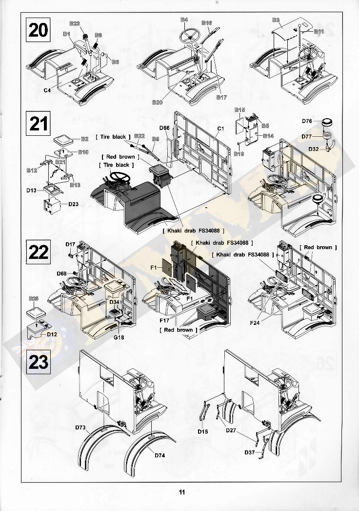
On the right side is the passenger seat (the seat cushion is part B26) with the air cleaner located underneath and there were no problems fitting these although you need to be careful the air cleaner pipe doesn’t extend past the rear edge of the floor so the rear wall will fit snugly. The engine compartment top cover is a separate part that fits okay but you may need to hold firmly in place as the glues dries for the best fit
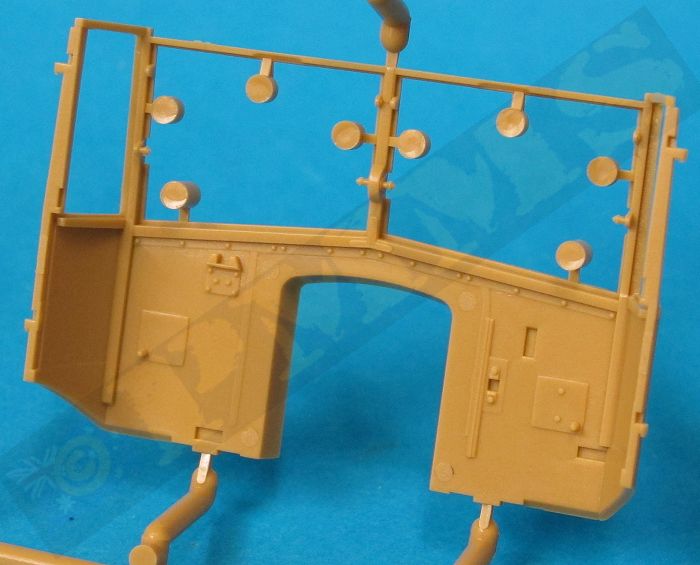
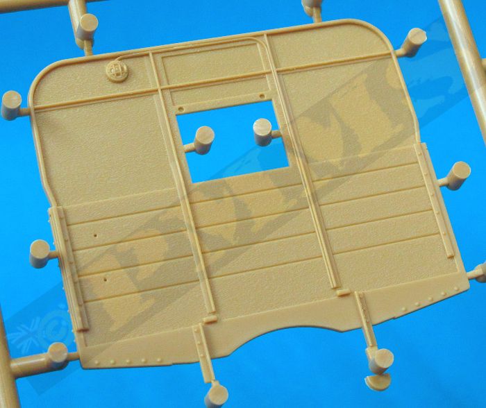
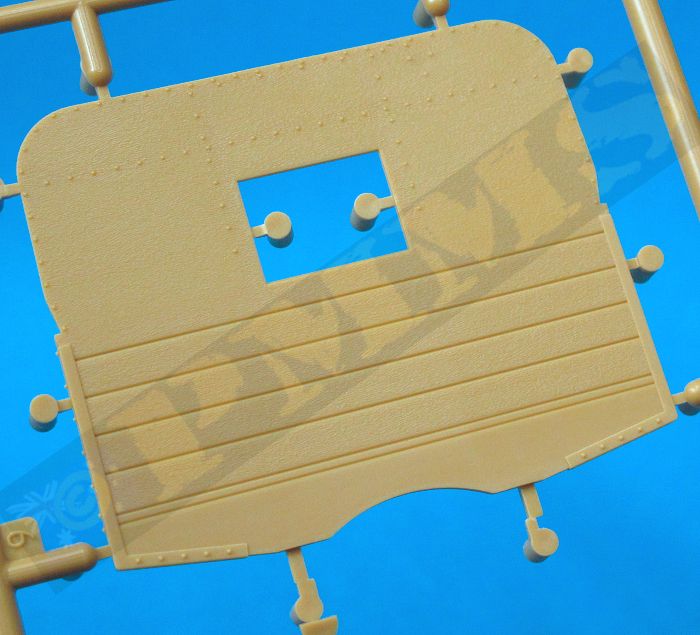
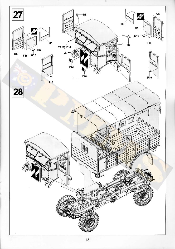
The rear wall has extensive ribbing included as well as seven small raised pins that need to be trimmed off before assembly, (see image d32) there are also some pin marks in-between the ribbing but only one (top left corner) is visible after as the other details added cover all the others so there is no need to worry about these. There is a large four part electrical control unit added to the right side with the cable cover fitted below, this unit has switches such as start, side/head light and battery cut-off switches, as well as the seven part seat and seat support and the padded seat backrests added to the wall. Care is needed when fitting the seat supports (parts B12, B13) as these trap the seat adjustment crank (part B21) between them but the rest of the seat assembly is straightforward with the assembled seat added to the lower wall.
The rear window has two sliding shutters (parts F1) and these can be fitted open of closed as required. Also fitted to the lower wall are the FWD lever (part B9) and auxiliary lever (part B22), I had the slightly trim the base of the levers to fit into the cut-out in the wall but this is only minor. The final items fitted are the two rifle racks with fine top clips on the left rear wall but there are no rifles provided to put in the clips and will need to find the rifles elsewhere should you wish to arm the crew? The fit of the floor and rear wall was spot on without any trimming needed and you should let this join dry before proceeding.
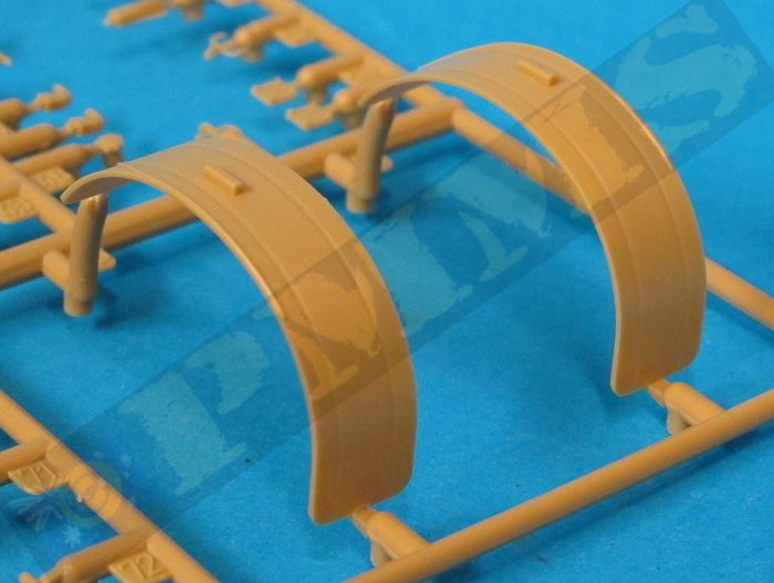
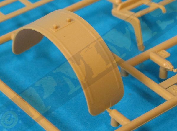
The two front fenders are added under the floor with precise locating lugs making fitting easy along with four very thin and delicate fender supports at the back, two of these also form the crew foot step for cab entry and exit. Removing these supports from the sprues without damage will require some care due to the very thin mouldings so take your time and use a very sharp blade when cutting.
The large front cab wall (part B26) is a single moulding that includes the side panels and the windscreen/window frames, the sprue attachments don’t overlap the window recesses like on the earlier cab so clean-up is a lot easier. The cab has excellent surface details included on both sides as well as the radiator mounting on the front; the radiator housing is separate and has two fine PE mesh grills that fit into the housing as well as a separate top filler cap. There is a small sink mark at the top of the housing between the grills that should be easy to eliminate. Another thing to note is there is no actual radiator behind the grills and from front on is very see-through so blanking off or making a radiator front for the insides could be an option?
On the inside of the wall is the instrument panel with decal dials but the fit of the panel needs the lower inside edge trimmed a little to fit the contours of the engine compartment properly when fitting the wall to the floor, test fitting will determine to amount to be trimmed. Also included is the brake controller under the instrument panel (part B7) and also a fire extinguisher with mounting on the right side (part B27).
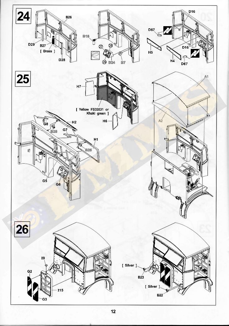
The main windscreens are in two parts either side with the fixed lower section and separate top section that can be positioned open closed, there are also fine PE brackets for the windscreen depending on the window position as well as wiper motors added to the inside top of the screens and I have fixed the left side windscreen open to illustrate this.
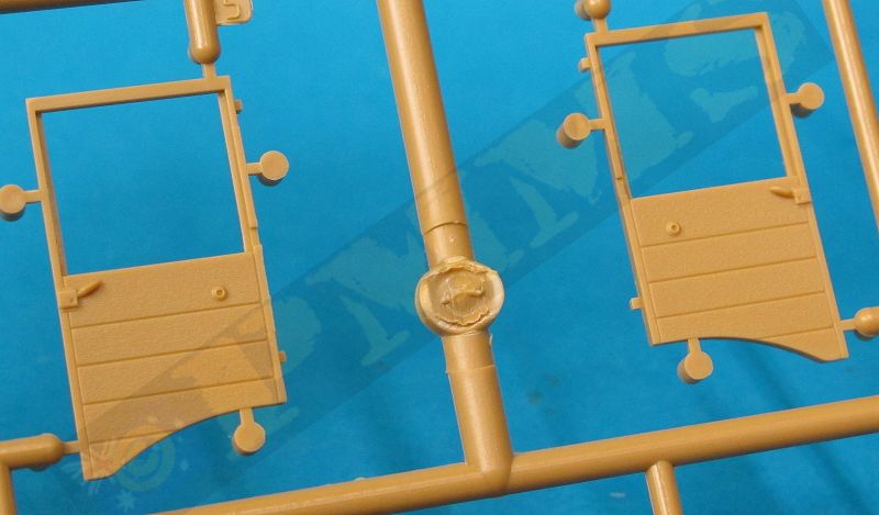
The two smaller side windows have the part numbers transposed, part H7 should be H6 and H6 should be H7 with the fit good after putting the windows on the correct side. There are separate central door hinges supplied, one if the door with fitted closed (part D16) and another if fitting the door open (part D67) so you should choose your preferred configuration and fit the appropriate hinge. The doors themselves have separate inner wood panels with very fine plastic door handles and window winder handle as well as fine PE grab handle for the inside that needs careful bending as there are no engraved bend guides included. There is alternate window ‘glass’ one full closed window and a partially open window for nice variation and again you simply choose you preferred option with the fit of the clear parts into the window frame being very good.
The fit of the front cab wall to the floor is excellent providing a very snug fit and when fitting the door in the closed position there is a large gap under the door and along the front edges, these gaps should actually be there and is not a fit problem as referring to any reference photo of the Matador will show. The final items added to the cab are the plastic windscreen wipers, rear view mirrors and small side lights, the mirrors and lights are best left till last as these can easily be damaged during handling if not careful.
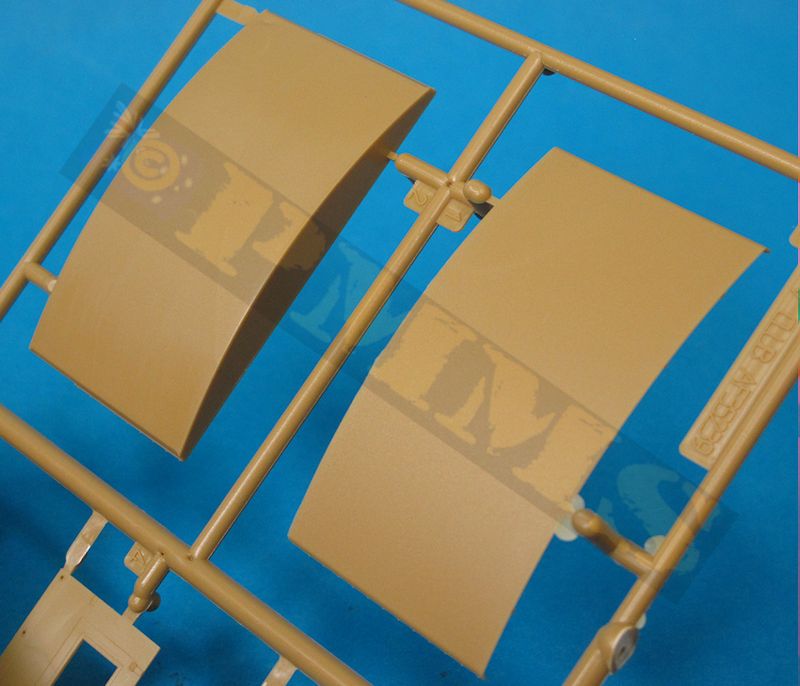
The new curved roof (part A2) with separate thinner top roof panel (part A1) is provided and the top panel has bevelled edges to give the appearance of the spacing and thinner edge but the bevel is quite steep and by reducing the thickness of the inside plastic for a more shallow bevel as well as thinning the edges of the roof a more realistic appearance can be achieved.
Another issue to watch for is along the outer curved rood edges is a row of very small rivets that unfortunately have a mould line running through the rivets and very careful clean-up is required to remove this mould line while not damaging the rivets. If you do accidentally remove some rivets on the process replacing these with Archer Surface Detail rivets would be an easy solution.
The two roof sections fit flush together, just make sure the front and rear edges are level as there isn’t any actual locating tabs but this is easy enough to do with the assembled rood fitting neatly to the top of the assembled cab.
Fitting the assembled cab to the chassis is fairly straightforward but I did slightly reduce the thickness and also bevelled the top edges of the chassis mounting brackets (parts I49, I50) to allow these to fit into the locating holes on the underside of the cab easier, this was only minor trimming so don’t remove too much plastic from the mountings. The two bracket parts F32 fit around the lower front cab tabs that sit on the front of the chassis frame for a snug fit. Care is needed removing parts F32 from the sprues as they do have quite extensive excess plastic around the brackets and it can be hard to see what the part is and what is excess plastic if not careful.
Of note is that the later style spaced roof with the open round hatch over the passenger position is also included (part B27) as is the half section of upper spaced roof (part B28) but these are not shown in the instructions as I presume intended for the Later Production Matador kit to come. But some photos exist of Mid Production trucks being fitted with this style of roof so the option is there if your wish?
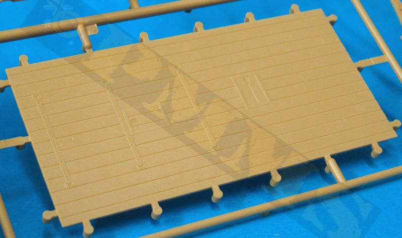
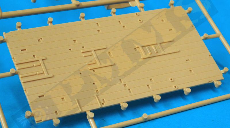
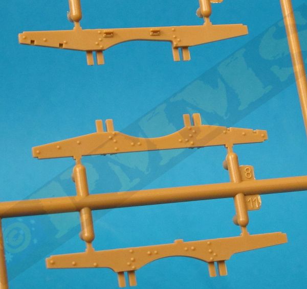
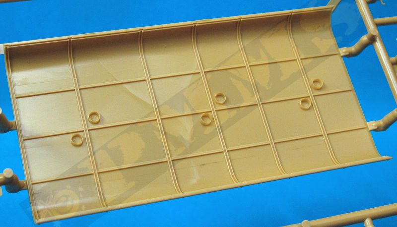
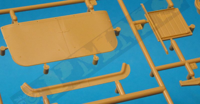
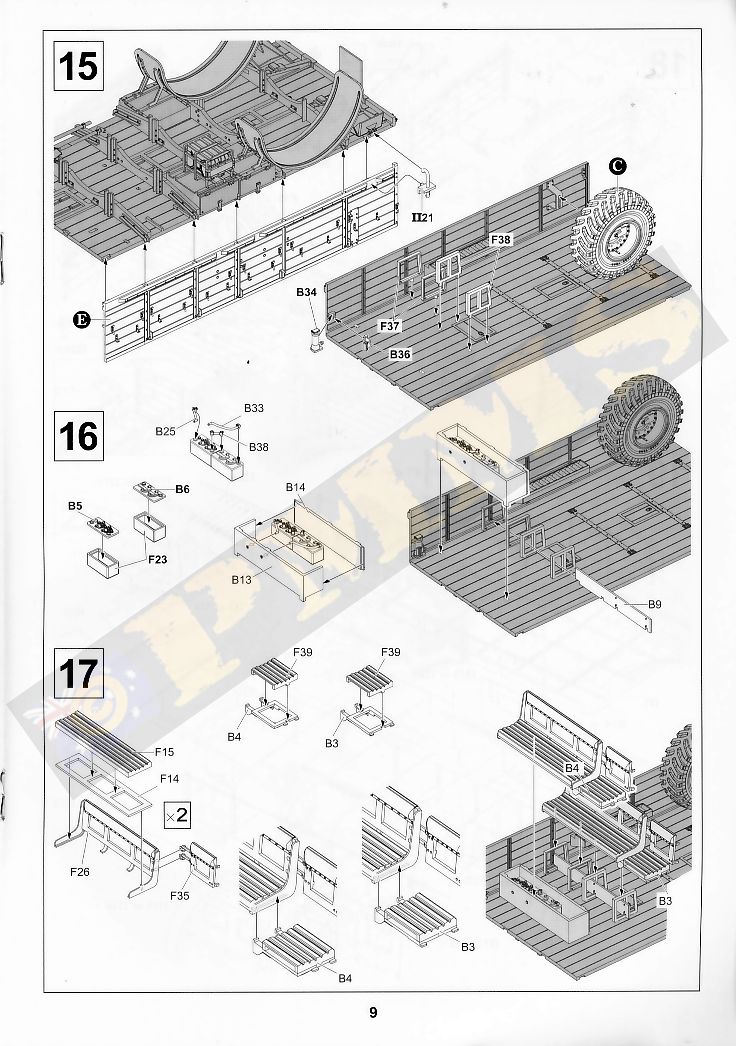
Details on the tray include the separate underside cross support beams, several storage lockers and the rear fenders with the two forward rows of wood slat troop seats also having nice wood grain texturing included plus the spare tyre rack in the rear right corner of the tray. The four fenders supports have four different parts so take care to positions these correctly as per the instructions.
Before starting there are some locating holes in the floor that need to be opened up, these are shown in the instructions (Step 10) and once done the cross member supports can be added taking careful note of the part numbers for each support and the direction for fitting the supports as C11 is fitted the opposite way around to the others. Added to the supports are small bolted strips and again you must watch the part numbers as there are two F8 and F11 with only very subtle differences so follow the instructions closely when fitting. Also added are the pioneer tools, forward edge strip and two parts F4, these can be left off until the side panels are fitted as the small central end bracket must align with the hook on the sides.
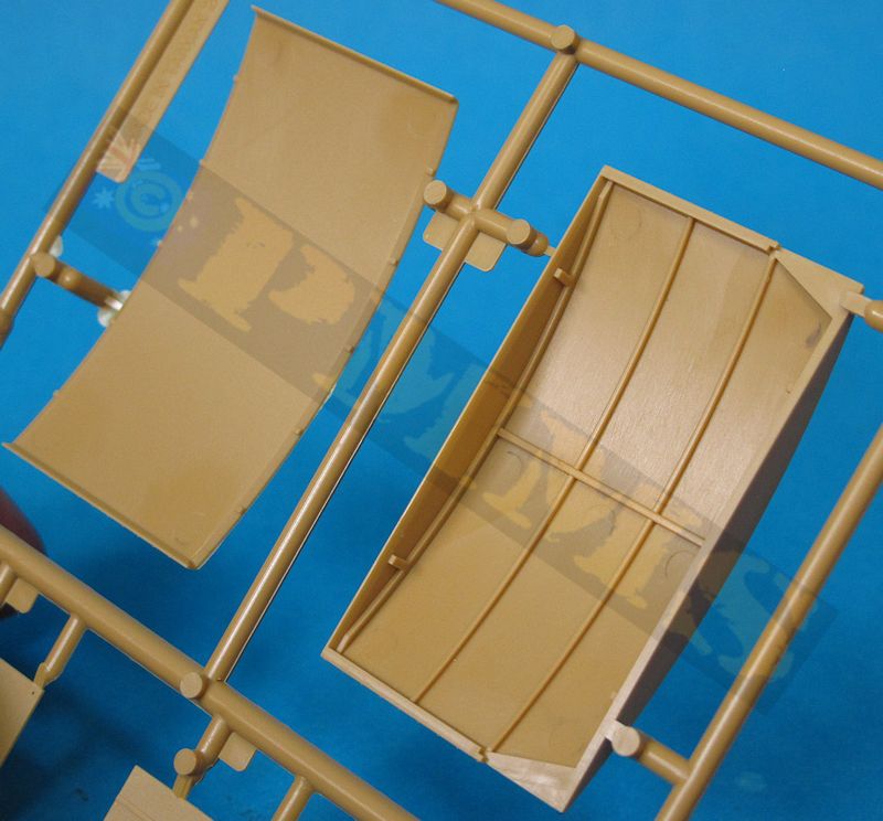
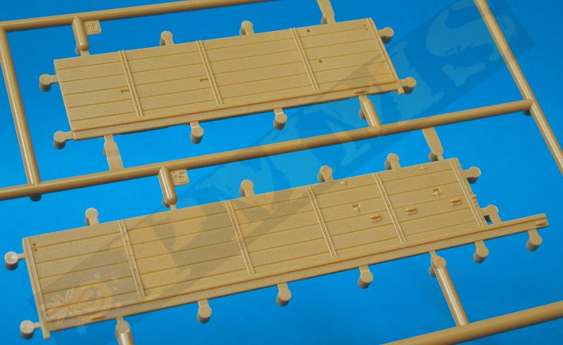
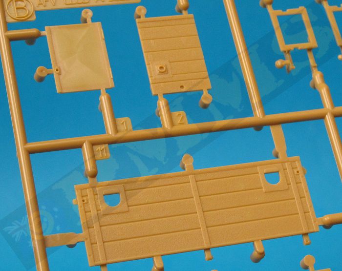
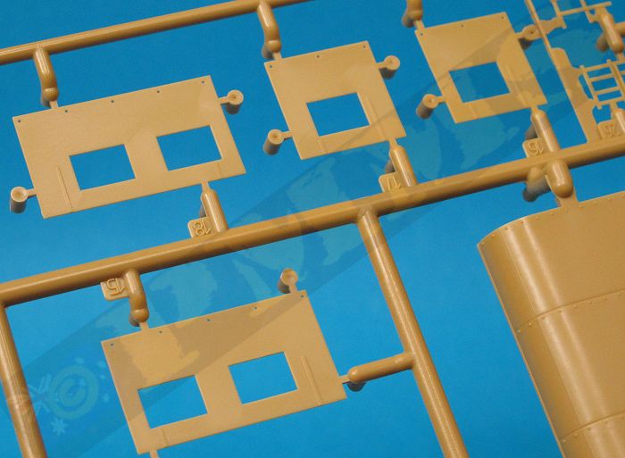
The two side panels again have excellent surface details with subtle wood grain and nicely rendered support stringers with rivet details, the left panel has a separate front entry door with separate handle and this can be fitted open or closed as you wish. The right side panels is made up of three parts, the main panel and two forward sections that are fixed into place and it’s best to glue these together to form the side panel before fitting to the floor for easier fitting. These parts are separate due the later production truck having a metal entry door on the right side which is not included on the early/mid production trucks.
Added to the panels are about 20 very small tie down cleats that need extreme care removing from the sprues and cleaning up the attachment bur before fitting to the panels using a fine pair of tweezers, along with the cleats are about 10 PE hooks that need careful bending to shape and then fitting and again patience and care are needed as you only get 1 or 2 spares so there is not a lot of room for error here but the resulting detail definition is impressive due the finesse of the plastic tie down cleats in particular. When fitting you must follow the instructions closely as the cleats and hooks are mixed together in random order and you want them in right place, hopefully?
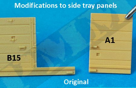
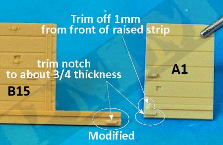
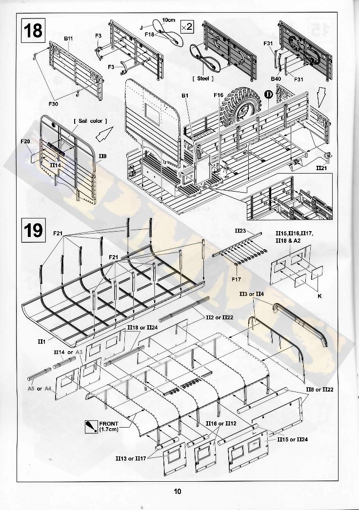
Fitting the side panels to the floor required some minor trimming for a proper fit, the locating tab on the inside of parts B15 and A1 needs to be reduced by about one quarter and a 1mm section cut from the raised strip on the inside of part A1, this is allow the front panel (part II9) to fit snugly,
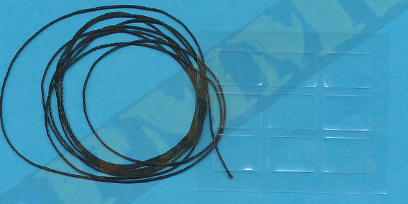
With these minor adjustments done the side and front panels fit perfectly to the floor without any further problems as does the rear tailgate which can be fitted open or closed are required. There are a few other smaller details such as rear gate hooks and two fine grad handles along with the cable brackets on the tailgate with the twine provided in the kit for the cable.
On the inside is the battery box with two nicely detailed batteries which are completely hidden under the front crew seat after assembly so you can bypass these if you wish? The seats themselves have excellent slat detail but assembly is a little vague when fitting the seat base and slats which in turn fit into the backrest part with the seats level with the front of the backrest side arms. Each seat has a smaller folding end seat added and these have small notches on the ends designed to mate with lugs on the inside of the left side panel but it was easier to cut off the seat tabs to avoid any alignment problems as there are no locating marks when fitting the seats to the battery box and seat supports. You could leave off the seats until after the side panel is attached and then align the seat tabs if you wished as another fitting option? The only other internal detail is the spare wheel mounting bracket and the spare wheel itself which is glued to the support bracket without any problems and the rifle rack base.
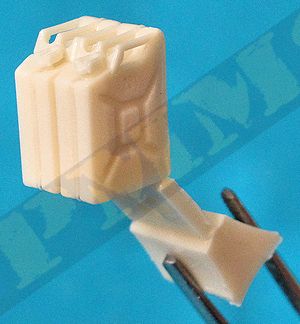
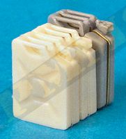
The kit provides two Jerry Cans moulded together in resin that also include the fine grab handles so apart from removing the casting block there is no other clean-up required. These new resin Jerry cans are again too short in height by about 1mm as were the previous plastic ones, the other issue is the corners of the cans are cast quite sharp and you will need to round these with a some light sanding for a better appearance. But with these Jerry cans fitted inside the under tray rack the height issue isn’t really obvious and these should do the job adequately, just use other proper sized Jerry cans if you wish to have these out of the racks in a diorama setting.
Also included is a small delicate PE oil can rack made up of seven small etched parts that need to be bent to shape and either soldered of glued with cyanoacrylate and I have not actually fitted this to the review build to avoid my head hurting as the rack will take some patience to assembly.
You may wish to fit the assembled rear cargo tray to the chassis before fitting the full metal roof as is a very snug fit and a bit of coaxing may be needed to get this into place. The reason I advised to cut off the four small lugs from the chassis frames at the beginning is because these are supposed to be locating lugs to get the tray in the right place on the chassis but AFV Club forgot to add the corresponding locating holes in the floor so they actually stop the tray fitting properly, hence their removal. To aid in fitting I bevelled out the ends of the locating brackets on the underside support beams to allow these to slip over the chassis easier as the square ends tend to stick on the chassis due to the very tight tolerances of the parts.
Using the position of the fenders and rear wheels as an alignment guide carefully press the tray into position over the chassis frames applying force equally front and rear until the tray sits evenly on the chassis frames, there is no need the glue the tray to the chassis and the fit is tight enough that it’s not going anywhere even if you lift the model.
from their recent SAS Jeep kit showing the difference in height as mentioned above.
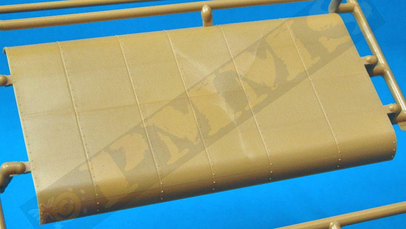
The metal roof has nice panel segment details and fine rivets but there is a largish mould seam line along each outer roof curve that will need to be carefully sanded making sure not to damage the rivet details on the panel joins.
Added to the inside right side is 10 very small rifle rack clips but again there are not rifles proved for these racks and again you will need to source the rifles elsewhere if required, note the racks are fitted at an angle and not upright as the instructions don’t show the clip angle too clearly.
The side support posts simply glue to small indents in the roof and you should let these dry completely before fitting the roof to the tray as the posts just butt join to the top of the side panels and it’s difficult to align these if the posts are still moving about. You may also wish to leave off the extended side flaps until after the roof is attached as some minor inside trimming may be needed to get a snug fit but test fitting will determine if this is required?
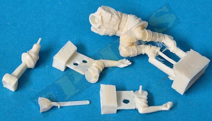
Clean-up is minimal and assembly straight forward and obviously if your are using this figure with the kit it would need to be added as you assembly the cab because it would be very difficult to fit it afterwards, the figure is also not shown in the instructions as its listed as a bonus and presumable will not be included in kits after the initial release?
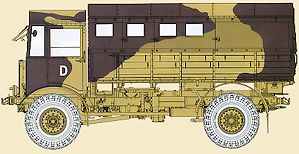
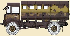
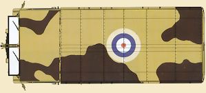
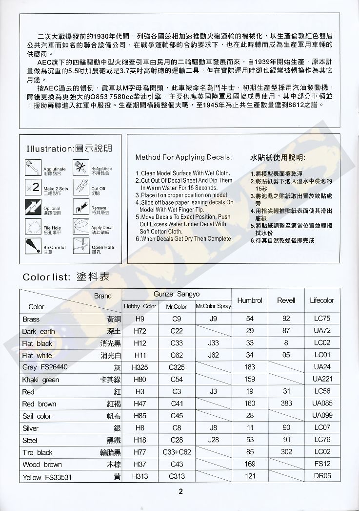
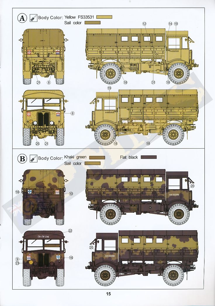
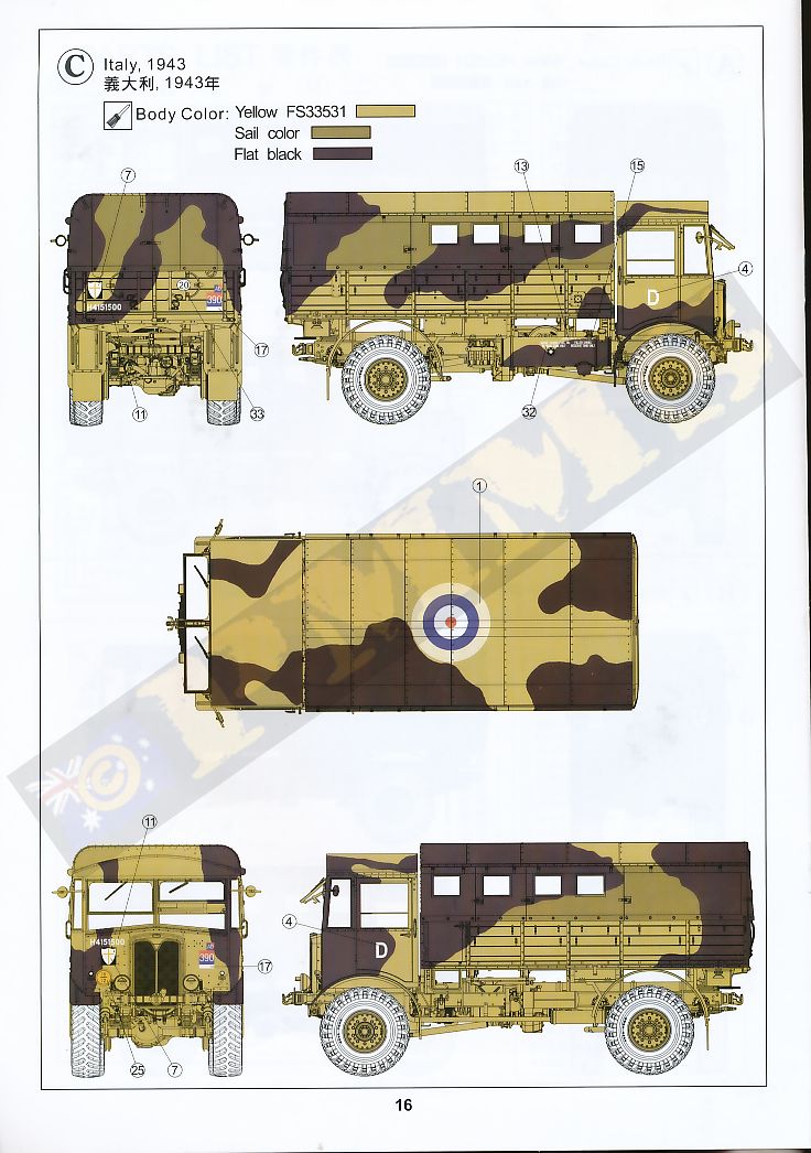
The biggest improvement with the instructions is AFV Club have now discovered colour printing with the front page and the painting scheme guides now in full colour as opposed to just B&W in previous kits and this does make not only for better presentation but the cam schemes are clearer as are the decal placements. The paper used is also better quality with a glossy finish again giving a more professional feel overall to the instructions.
|
Some of the parts are extremely delicate and need care in handling and during assembly with the kit offering numerous alternate configuration options such as the open of closed windscreens, doors and rear cargo tray side flaps. There is scope for adding additional details such as the chassis air and fuel tank plumbing as well as brake lines etc. to really detail up the model. The new roof gives the “classic” Matador appearance for the most widely used version of the truck in just about every theatre of operations.
But overall this is superbly done kit which should be welcomed by Allied modellers and we can look forward to the later production truck coming as most of the parts required are already included as mentioned and also hopefully other versions such as the 6x6 AEC Model (0)854 and maybe the Deacon”seeing as AFV Club already have the 6pdr kit done.
Rating 9.5/10
Click on thumbnails for larger view
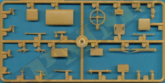
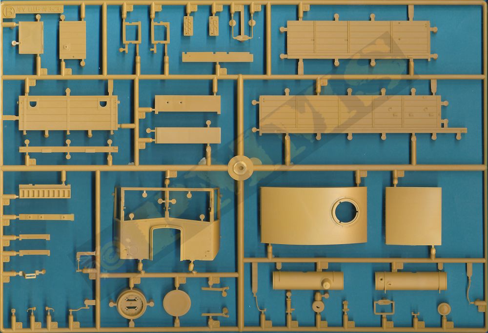
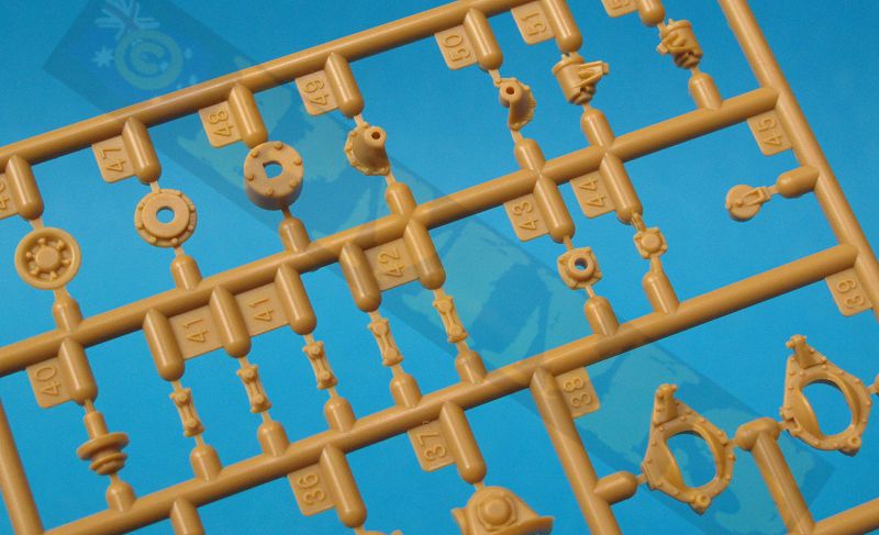
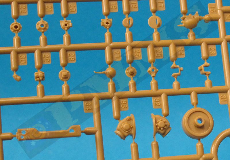
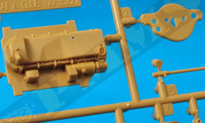
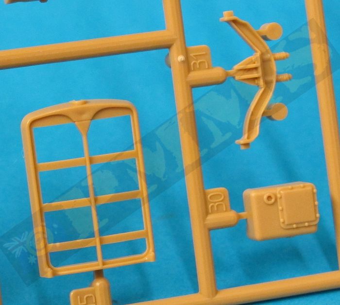
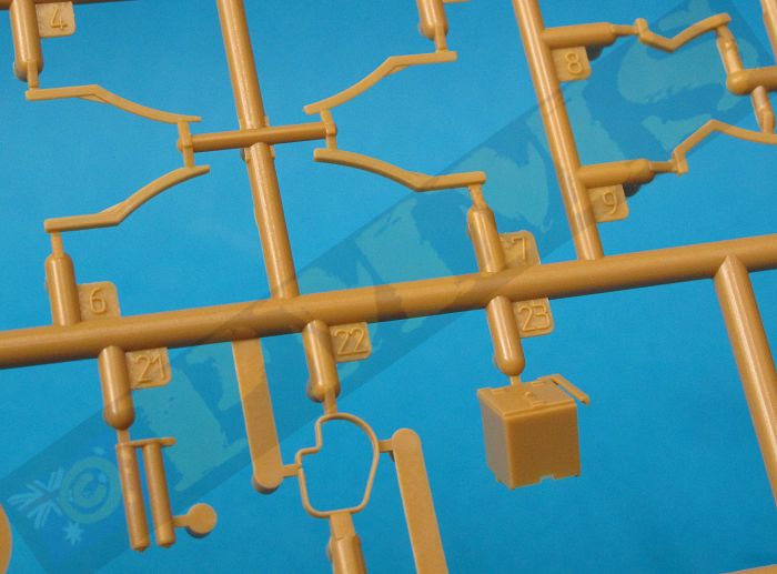
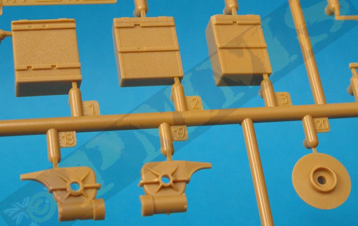
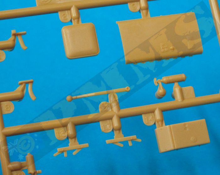
Kit Sprues
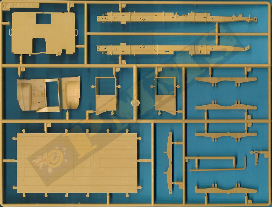

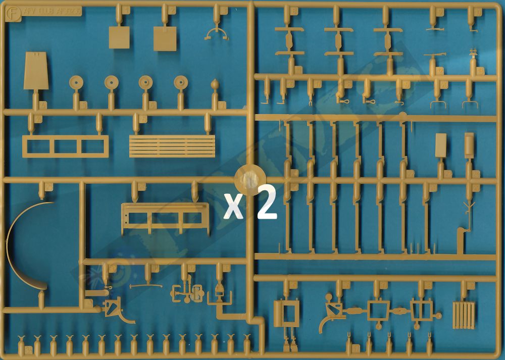
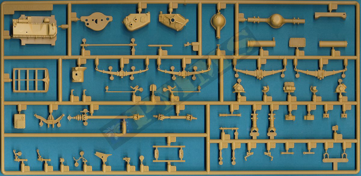
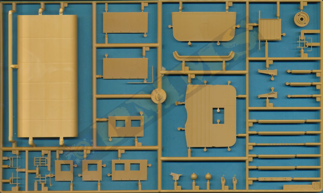
Sprue detail images


Instructions


Close new window to return to review
| AEC Matador Taking the Rough with the Smooth ISBN: 978-1-904686-24-8  |
British Military Trucks of WWII Tankograd Publishing ISBN: 978-3-936519-29-7  |
 and
and Please to help the reviews to continue, thank you
