
M-10 Tank Destroyer
AFV Club Kit No. AF 350241:35th Scale
Build Review
by Terry Ashley
Overall the kit has excellent details with a very busy interior. You will however, have to revert to some basic modelling skills in some departments to achieve a result.
The kit has 358 styrene parts in olive drab on 8 sprues. Moulding is crisp with little or no flash evident. More on the details as we go along. The tracks are the T49 steel block type in a soft continuous band. An aluminum barrel is provided along with a small spring for barrel recoil. A length of twine for the towropes and the decal sheet plus the instruction sheet finishes off what’s in the box.
Step
1: Hull Interior:
Construction begins with
the lower hull "bathtub" which has the front transmission cover as
a separate piece, just like the real thing.
The side sponsons have ammo racks included with separate round canisters to add later. There are some fairly large ejection pin marks here, but fortunately they are all raised for easy removal. The rear firewall has nice details moulded on. This is attached to the floor plate (part B4) which includes excellent tread plate pattern. This assembly is then fitted to the lower hull.
The forward section has the two seats on their mounts and a central drivetrain hump. A radio and driver’s instrument panel with nice details is added to the side sponsons. No fit problems were encountered with any of these parts, careful painting and weathering will bring out the details nicely. The only major omission here is the exclusion of the driver’s steering levers.
Views of model during construction
Click for larger view, click BACK button to return to
review
Step2
and 3: The Front Transmission Cover:
This has nice exterior details
with casting numbers included. To the inside of this is added the transmission
cover plate and a full gearbox. The detail here is again excellent with no
fit
problems. This assembly is then added to the main hull.
Care is needed when fitting the final drive housings. There are no location pins and the locating marks are a little vague. The housings themselves appear to be a little undersize. But this isn’t that noticeable when the sprockets and track are fitted. The center securing plate on the drive sprockets are separate pieces, unfortunately the bolt head detail is a little lacking. Also the locating pin on the two halves of the drive sprockets don't line up, you need to remove the locating pin and align the teeth by eye.
Finally the two front towing lugs (parts F11) don’t sit at the correct angle. I had to make slight alterations to the locating holes in the transmission cover to get them sit right.
Obviously all the interior details should be painted before the hull top is attached.
Step
4: The Suspension:
You get the Type 2C-1 Intermediate
Standard VVSS suspension. It is without doubt the best VVSS suspension I have
seen in any kit to date. It is fully articulated and has excellent surface
texturing
and detail, right down to the casting numbers and grease nipple detail on the
wheel faces.
Unfortunately there is a down side. The road wheels, which are moulded as a single item, are hollow at the back (minor point) the main problem being large sink marks around the center of the rubber section. This required some extensive use of model filler to get an even finish to the roadwheels. After this time consuming exercise the rest of the construction went ahead smoothly.
Follow the instruction carefully and you should have no problems. Also take care not to get any glue where it shouldn’t go if you want the units to articulate correctly.
Step
5: The Rear Hull Plate:
This is straightforward
apart from the idler wheel mounts (parts B18,19). Again the locating points
for these are vague, the square locating lug allows a fair bit of movement
and
there is no locating marks on the hull side for the idler mounting plates (parts
B20, 21). Care should be taken to line both sides up correctly. The rear plate
should be attached to the hull and allowed to dry thoroughly before adding
the
hull top.
Step
6: Lower Hull Completion:
It is a simple matter to
attach the six VVSS units to the lower hull. The locating points here are very
precise unlike some others as outlined above. Set aside to dry well.
Steps
7 to 9: The Upper Hull:
This is a single moulding
except for the rear plate. There is excellent surface texture with some nice
weld seam detail around the turret ring and hatches. The side "skirts" are
included in the upper hull. Some nice engineering has been done here to achieve
this, the mould lines on the inside indicate a three part mould has
been used to good effect. This technique results in the lower edges of the
skirts being very thin and care has to be taken not to damage them.
The rear plate has a fairly prominent join line when attached. This is actually a weld seam on the real vehicle and could do with a little additional detailing to "hide" the seam by the modeller.
The engine deck is a separate piece. While you could say this makes including an engine easy, I feel it has a different purpose (and well thought out by AFV Club). When attaching the upper and lower hull sections there are two small lugs on the lower hull which must "mate" with lugs inside the upper hull to get a secure fit. I found during dry fitting that if you leave the engine cover off you can easily see these locating points, but if the cover is attached it is very hit and miss with you having to "feel" your way to a good fit. So, leave off the engine cover and make life easy when attaching the hull sections. Simple fit the engine deck cover after the hull sections are together.
Many small detail parts are added to the hull top, all of which have excellent detail. The many bolt heads are in two pieces each for good definition. It is fairly fiddly and time consuming to remove all these from the sprues, but the end result is worth it. A few of the rows of bolts appear to be slightly in the wrong places according to some photos. I’m not sure if the layout of the bolts differed between production batches and variants. Either way, with the bolts as separate parts it’s easy to realign them if you wish according to you available reference sources.
It should be noted that when an M10 (or M4, M5etc) is fitted with the steel cleat track they usually don't have the spare grousers mounted separately. The steel track adds enough extra weight without adding more with the grousers as well. As with anything you'll probably find an exception somewhere.
The two front hatches are superb. They have separate periscopes, which are fitted into cutouts in the hatch along with separate covers. The hatch hinges are in two pieces each to give good definition. It would be easy to make these operable with some careful drilling with a pin vise. I thinned down the head light and tail light guards for a more realistic appearance. All the tools can be attached now or after painting, whichever method you prefer.
No problems were encountered here in fitting these parts.
Views of finished model
Click for larger view, click BACK button to return to
review
Step
10: Turret:
This represents the Mid-production
turret with the triangular counter-weights.
This area is again very well detailed. The lower turret section is in one piece
with some nice bolthead detail around the turret ring. There are some more prominent
ejection pin marks here, but again they are raised and easily removed. One point
to watch is the locating marks for the rear wall ammo racks. They are at the
wrong angle. The two each side should be parallel with each other and not converging,
as the locating marks would have it. Added to the turret ring is the seats and
turret rotation wheel.
The three turret wall sections also have the large raised pin ejection marks, which can be easily removed. Added to the parts are a number of other details. Some of these are simplified (main sight B17) and could do with some extra detailing by the builder.
Again there are separate boltheads to be add to the outside of the turret. The three large lifting eyes (parts F3) are completely the wrong shape and should be reshaped or replaced.
The rear counter weights had some minor sink marks around the edges. Filling these unfortunately eliminated the nice surface texture of the parts. Care is needed when fitting the upper walls to the lower turret section as no locating pins are provided. This may require care to fit but any pins would be very noticeable in the open turret, so any minor inconvenience here is worth it for a better appearance later. You should also take care with the joins to get a good fit, there are weld seams inside and out on the real turret so any discrepancies could be covered by adding weld seams.
No ammo is supplied for the turret racks, a bit of an omission. The plans advertise the AFV Club set No AF35018, which contains turned brass rounds and shell cases. This is shown as containing 76mm and 3" rounds. Unfortunately the 3" shell cases used on the M10 had a pronounced bulge just behind the projectile, which isn’t present on the rounds in this set. It would have been nice to have some rounds included in the kit, as the mounting brackets are very prominent when viewing the turret.
Step
11: 3" Gun Assembly:
This is, in a word
brilliant. The main gun is in two pieces, upper and lower. Trapped between
these is the aluminium barrel with its return spring. This actually does recoil
if
you push back on the barrel, but really, are we going to sit there pushing
the barrel back and forward after the kit is finished?
Added to the main gun are many smaller items including the separate breechblock, crew guards and rotating wheels. This builds into an impressive assembly. The front mantlet has excellent surface texture also which includes casting numbers and separate cover for the main telescopic sight.
The turret interior and gun assembly should be fully painted and weathered before proceeding to the final turret assembly.
Step
12: Final Turret Assemble:
It’s a simple matter to trap
the gun assembly to the lower turret assembly with the top turret plate (part
A3). No fit problems were encountered apart from the comments above.
TAKE NOTE: The turret does not have any locating tabs, but just sits snugly in the turret ring cutout. This means if you or anyone picks up the model and turns it over, one turret will rush rapidly towards the floor.
Step13:
The steel rope assembly
is self-explanatory, the instructions saying it all.
Step14:
M2 .50cal Machine Gun:
This is a very nice .50cal
as far as kit supplied guns go. It is nicely moulded with separate cocking
handle and mounting plate and separate rear firing handles. The ammo box is
in three
pieces with a separate row of ammo to go between the box and the gun.
Step
15: Final Assembly:
The kit supplied tracks (T49
steel block type) are fitted here, although I left these off until after final
painting. The detail is excellent with the end connectors in the right place
and you can see daylight between each link.
The
Decals: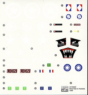
Unfortunately, the colour
register is all over the place and they are slightly thick. There are markings
for two US and three French M10s from WWII and one ROC vehicle from 1958. The
ROC M10 was fitted with a muzzle brake, but you don’t get that in the lit.
Painting
and Weathering:
The hull interior was painted
Matt white with the fighting compartment floor in olive drab. The turret interior
was entirely olive drab with detailed painting as needed. These were all painted
and weathered during construction and before final fitting of the relevant
sections.
After masking off the hull openings, I airbrushed an overall coat of Humbrol Enamels No.155 Olive Drab. When dry I applied the markings. I didn’t use the kit decals, but used rub on stars from various Verlinden sheets. The unit markings were added by firstly removing the decal from the backing sheet in the usual manner. I then dried the decal on a tissue and painted (with small brush) Matt clear where the decals were to go. While the paint is still wet, I laid the decal down in the required position. Light pressure with the brush was applied to sit the decal down. After the paint dries the decal is firmly in place with no air bubble "silvering". I have found this method very handy for small markings found on many AFVs. Sure beats glossing the whole area just to apply a small decal.
I then airbrushed an overall coat of Matt Clear to seal the decals and paintwork prior to weathering. After leaving for 48 hours to dry completely, I weathered the model by applying a wash of thinned oil paint (Raw Umber) and finally various drybrushings with lighter earthy colours to bring out the details and a light overspray for the dusty effect.
Conclusion:
In my opinion this
is and excellent kit of a much wanted subject. It has some very nicely done
fine details as well as other good features. As with any kit there is room
for
improvement, but isn’t that what modelling is all about?
For mine, the inclusion of brass sheels and workable track as offered by AFV Club as separate kits would have made this a very expensive kit. Also, we modellers never have a problem buying track link sets (ModelKasten etc) and other detail sets for our kits. The fact that the additional sets offered here is by the same company, well I don’t see as a problem. After all, we all trying to make a buck and a kit company can’t make a profit then they don’t exist.
But having said all that it would have been nice see a few plastic rounds for the rear turret walls, as these are very prominent and easily seen from the outside.
Finally, the pros far outweigh the cons during construction. I would recommend this kit to anyone, most U.S. Armor fans won’t need any convincing anyway.
News from Hobby Fan is they are working on an M10 interior update and no doubt people like Verlinden are hard at work as we speak. But apart from some fine detail tweaking I don’t think this kit really needs a full interior replacement.
Go to it, a great kit.
The Sprues:
References:
Click Browsers BACK button to return to list