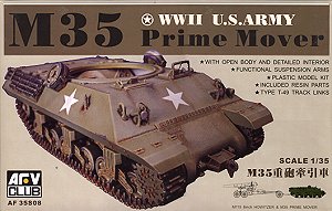
M35
Prime Mover
AFV Club Kit No. AF 35S08
1:35th Scale
Construction Review Part 1
by Terry Ashley
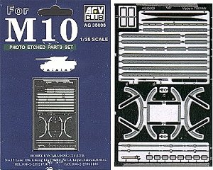
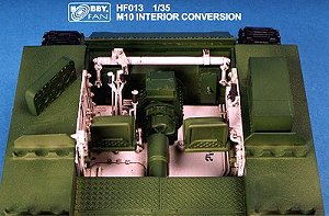
Additional detail sets used in construction
|
Click on picture
to see the resin pieces
Click Browsers BACK button to return to review
|
History:
With the planned invasion of Europe beginning on D-Day, the
need for adequate transport for the heavy artillery pieces became apparent.
Initially, M31s and M32s were converted to prime movers by removing their turrets
and installing winches, these being renamed M33 and M34 respectively. Between
January and June 1944, 209 M10A1s, which were being used for training, were
also converted by removing the turret and internal ammo storage and other fittings
to become the M35 Prime Mover.
While AFV Club show their kits of the M59 155mm Canon and M115 8" Howitzer as
being towed by the M35 in the instructions, this is not entirely correct. The
M35 was used primarily to tow the 8" GUN M1 or the 240mm Howtizer M1, these
being different weapons altogether from the kits mentioned. (Thanks to Peter
Brown for the good oil here)
The
Kit:
AFV Club
has now released this vehicle as a follow on from the earlier M10
Tank Destroyer.
Unfortunately AFV Club have done themselves no favours by simply releasing
the same kit minus the turret. The major problem is the "small" fact that the
M10 and M10A1 hulls are not the same.
The M10 was powered by a diesel engine while the M10A1 used a gasoline engine.
This resulted in the M10A1 using the larger louvered engine bay covers of the
M4A3 and fuel filler caps in different positions from the M10. The arrangement
of the engine exhausts on the rear hull is also different due to the different
power plants.
AFV Club obviously knew this as it mentions this fact in the instruction
sheet notes. Also one of the diagrams in the instructions show the correct full
width engine covers (step 11), while the section showing the assembly of the
rear hull has the narrow doors included in the kit (step 9). This all makes
the omission very puzzling?
Construction:
I will attempt
to show here what is required to produce a more accurate M35. The vehicle itself
is not well documented with the same few photographs appearing in numerous
publications.
Variations of minor fittings and storage is very common, the only "given" is
the use of the M10A1 hulls for all M35s. The construction steps here do not
necessarily follow the kit instruction steps.
Of course this conversion could be used to produce an M10A1 from the AFV
Club M10 if you wished?
As I prefer to
do any major surgery before commencing the normal kit construction the first
and most obvious is to correct the rear hull arrangement. If you have a spare
Tamiya (or Italeri) M4A3 lying about it will make the job a little
easier.
Step
#1:
From the rear hull
remove the entire engine deck panel (not just the louvered doors) as well as
a section 4mm past the rear line of
 |
|
Image #1
|
the engine deck. This will
need to be done with some care as the fuel filler caps and the bolt heads need
to be saved to re-attach to the new rear deck.
After cutting out the panels with a sharp modelling knife, remove the bolts by
slicing off with sharp blade. The fuel filler caps were cut from the rear deck
still with the deck plastic attached, this was then sander off on a sheet of wet
and dry paper on a flat surface much the same as sanding the backing of resin
parts.
The two caps located outside of the engine deck were cut out entirely and the
resulting square filled with a spare bit of decking. The locating hole for the
barrel lock will also need to be filled as well as the locating marks for the
hull side bolts as these were not fitted to the M35.
NOTE: the large bolts were on the front glacis but not the sides contrary to the
box top illustration. (See Image #1).
Step
#2:
 |
|
Image #2
|
The resulting hole in your
kit part is actually 4mm too wide for the new engine deck.
To fix this and also to ensure the side cutouts are smooth, glue a strip of 2mm
plastic beam to each side of the cutout area. The kit panel line extending back
to the rear of the hull will need to be filled and a new panel line scribed 2mm
in from the original. (See Image #2).
Bolt heads were repositioned inside the new rear panel lines and lifting handles
added from thin wire.
Note: After cutting out the engine deck I attached the rear hull panel (part
E3) to give rigidity to the rear hull as it can flex a fair bit with all the plastic
just removed.
There is a small cutout at the bottom of this rear panel that has to be filled
with plastic card, as it is not present on the A1 hull. (See Image
#8).
Step
#3:
Firstly remove the engine deck from the Tamiya M4A3 kit
along the panel lines on the kit and sand off the moulded on fuel cap. A small
section of 2mm beam will need to be added to the front corners of the Tamiya
deck to fit in with the cutouts on the M35 deck. I then replaced the door handles
with thin wire.
 |
|
Image #3
|
After test fitting the deck
(several times) to ensure everything lined up correctly, the new deck was glued
into place.
After the glue on the new deck has dried and the seams checked for any blemishes,
the fuel filler caps can be added. It is best to measure and mark the position
of the caps with a soft pencil (they are placed centrally between the hull side
and edge of the new deck). There are only 5 caps used not 6 as on the M10.
Finally add the bolt heads from earlier, note their position on the Tamiya
parts before removal, as they aren't evenly spaced.
Add the fire extinguisher housing noting that it is level with the side hull and
not on an angle as with the M10 hull. (See Image
#3).
The rear exhaust panel that hangs down from the upper hull is also taken from
the Tamiya kit. After making adjustments so it fits correctly (hangs down
vertically) cement this to the rear hull. (See Image
#8).
Step
#4:
We now turn to the lower hull. I replaced the road and idler wheels with those
from the Academy M12 kit as they have nice interior detail while the
AFV Club wheels do not. These fitted to the AFV Club suspension
units without any modification.
 |
|
Image #4
|
(This is not essential, but
a personal preference). (See Image #4). The
AFV Club kit supplies the fancy drive sprockets (with cutouts) while all
photos of M35's I have seen have the later Type 3 'Simple Plate' drive sprockets
(solid with no cutouts). I again turned to the Tamiya M4A3 kit for the
solid sprockets. These required the rear locating hole enlarging to fit the AFV
Club kit axle.
There is an annoying little sink mark in the center of the Tamiya drive
sprocket that I filler by adding a small plastic card disk. (See Image
#5).
On the rear panel the engine compartment door was added from plastic card with
wire handles and etched brass hinges. The exhaust outlets were also taken from
the Tamiya M4A3 kit. (See Image #4).
I decided to use the rubber block track from the Tamiya M4 kit for a bit
of verity if nothing else.
Step
#5:
We now turn to the remaining
external details on the upper hull. The weld seams at the front and rear corners
of the hull were
 |
|
Image #5
|
added with thin sprue soaked
in liquid cement with texture added as it dried. The front and rear light guards
were added from the AFV Club M10 etched set. This is in stainless steel
and if you plan to do anything with the parts they must be heated (red hot) in
a candle flame to make them pliable.
The tool brackets were added from various Eduard etched sets (their M10
set was released just after I finished the kit, always the way?) with the tool
straps from the AFV Club etched set. (See Image
#8 & 9).
Finally the remaining Hobby Fan resin bits were added, the side spare idlers
and the front towing bracket, added using thick super glue.
Step
#6:
The interior was dressed up using the new Hobby Fan M10
interior set. This is fairly comprehensive and was installed without modification.
The floor casting is in one piece, I did cut this in half to make fitting easier,
the cut being hidden under the transmission when installed.
As with any resin parts regular dry fitting will make life easier, some minor
trimming was needed to get a snug fit. (See Image
#6 & 7).
Other interior modifications included removing the moulded on ammo racks on
the side sponsons and rear bulkhead (these were not fitted to the M35)
 |
 |
| Image
#6 |
Image
#7 |
 |
 |
| Image
#8 |
Image
#9 |
Other than that,
the same construction comments apply to the M35 as with the original M10
kit review, except for the turret of course.
Go to Part
Two - Painting and Finishing.
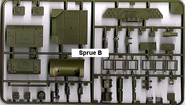
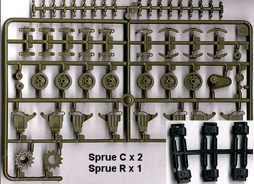
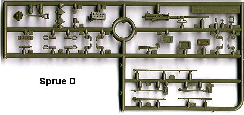
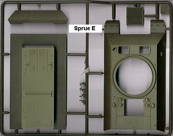
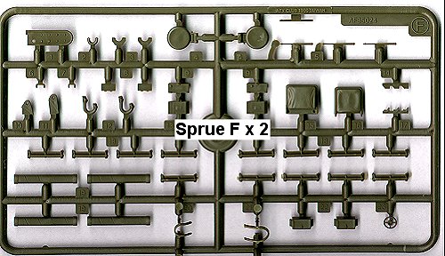
The
M35 Kit Contents:
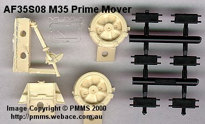
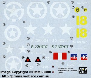
Click
on thumbnails for larger view
Click Browsers BACK button to return to page
References:
Click Browsers BACK button to return to list
Home / Reviews / Vehicle
Reviews / AFV
Club