
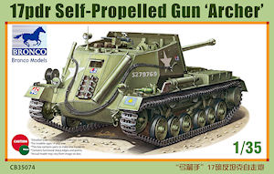
17pdr Self-Propelled Gun 'Archer'
Bronco Models 1:35 Scale Kit No. CB-35074
Kit review by Terry Ashley

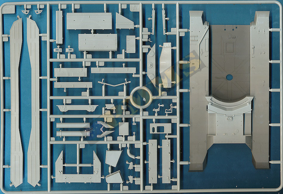
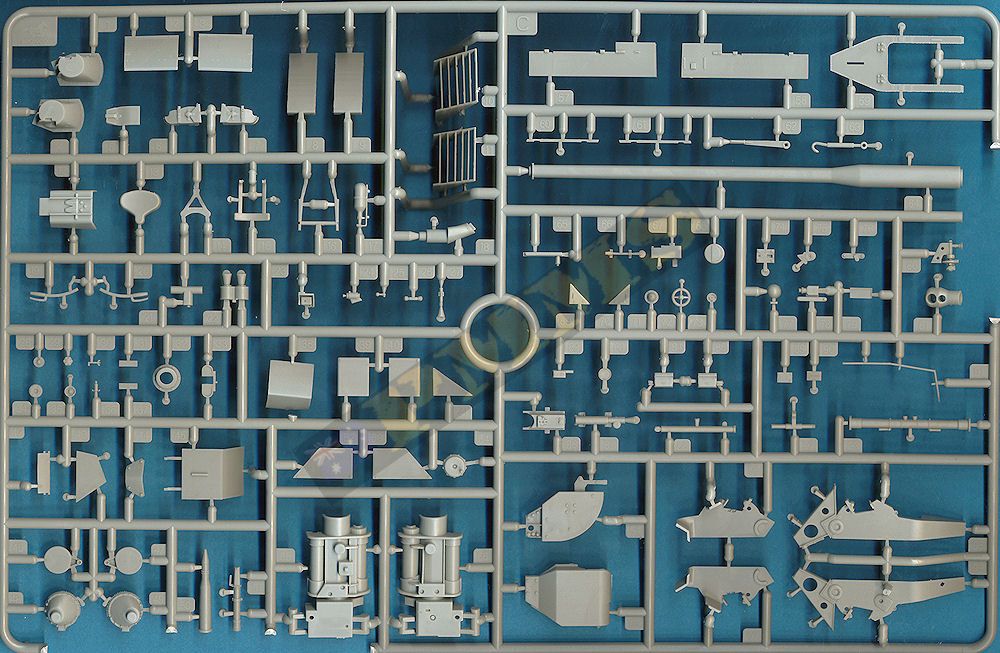
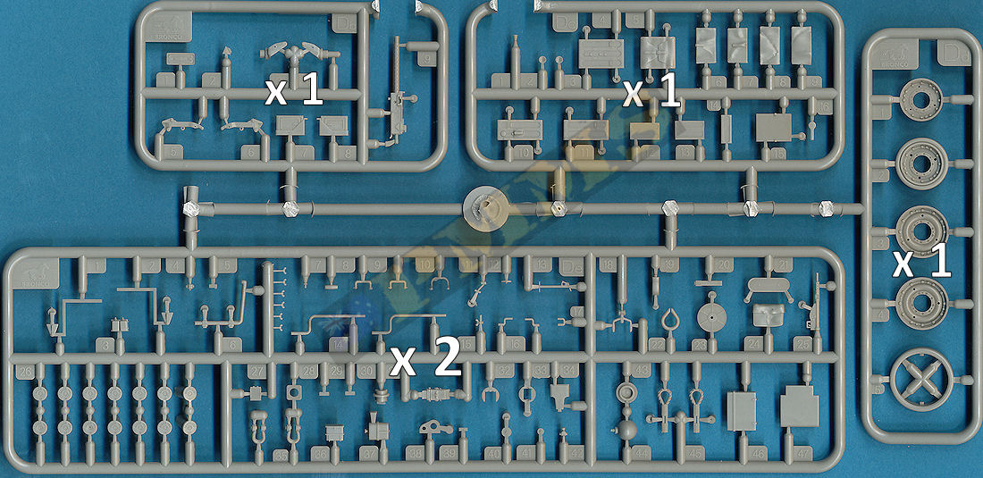
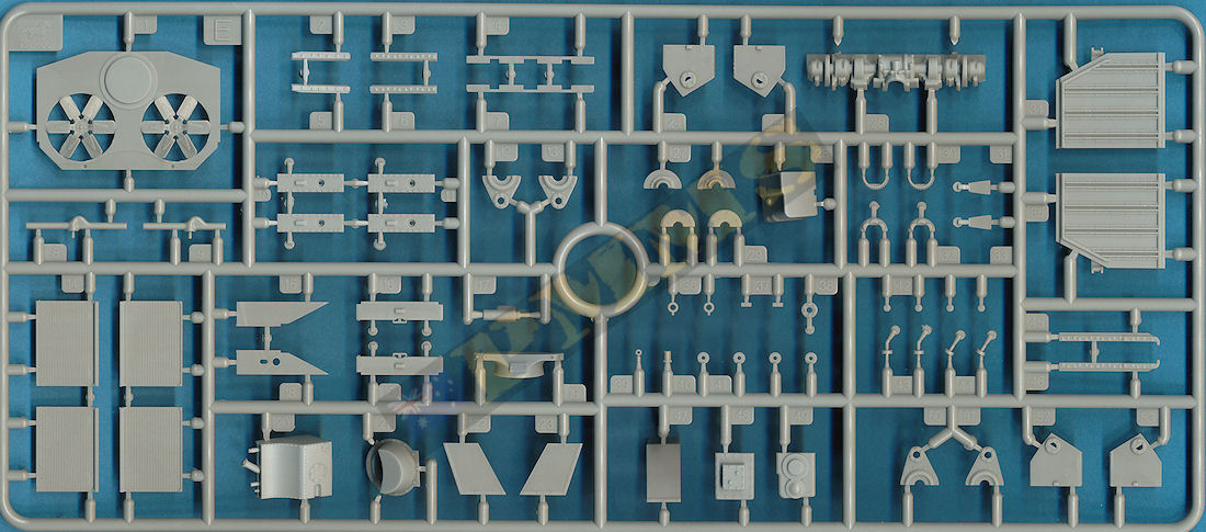
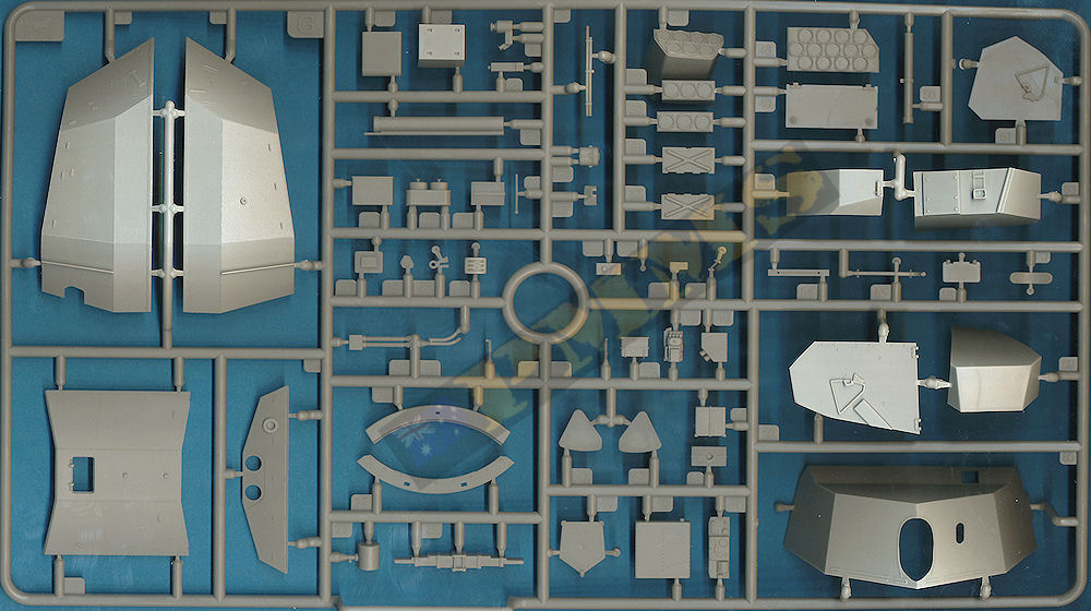
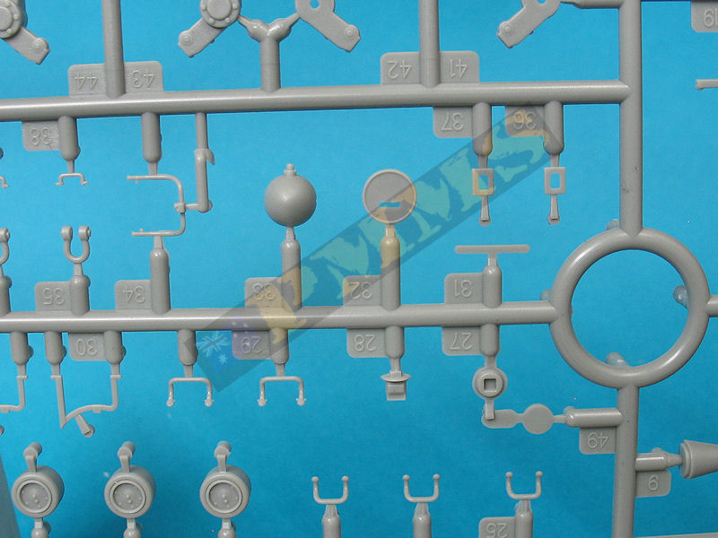
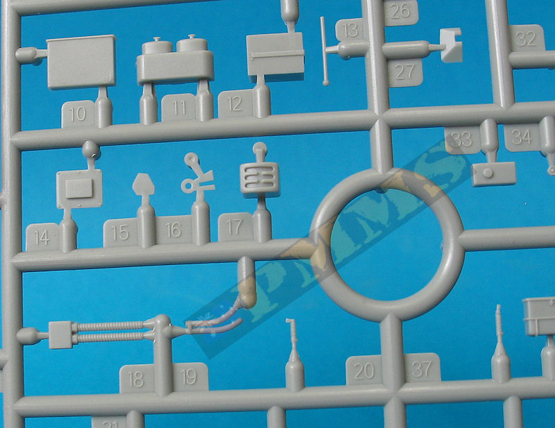
The standard of moulding is extremely high with clean crisp detail, virtually no flash (just the odd bit on some of the smaller parts) and just a few shallow pin marks that would be visible after assembly. The many very small parts both plastic and etched require care removing from the sprues and in handling but these add a high degree of detail definition to the assemblies.
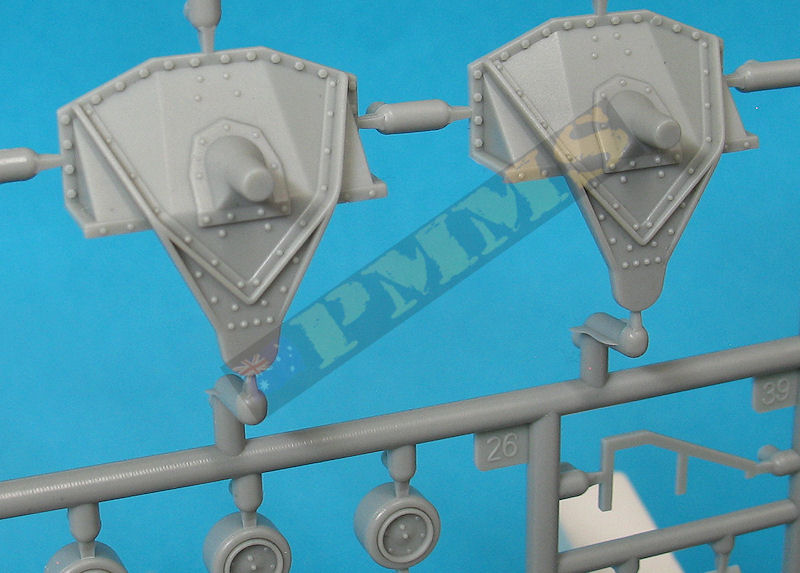
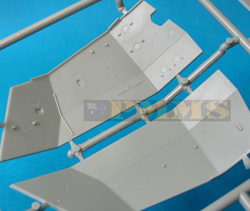
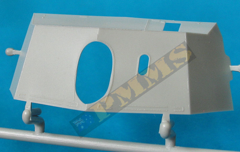
Detail on the parts is also well done with the weld seams on the superstructure panels being on both sides along with fine rivet and panel line details. The many moulded on tie down cleats can be replaced with small etched cleats for greater definition should you want and the individual workable track just adds to the detail definition.
The kit itself gives a choice of early or late production with the instructions calling out the alternate parts so decide which version you want to build and check the instruction steps closely to use the correct parts. There are also new road wheels, still the same size as the previous Miniart wheels but with a different wheel pattern but more on this later. There are a couple of other dimensional discrepancies in the kit but nothing too get excited about as we will see.
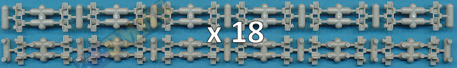
Being an open top vehicle you get a highly detailed fighting compartment interior that includes many multi-part sub-assemblies with extensive use of etched parts that results in excellent detail definition. Added to this you get the rear engine bulkhead with twin fans included plus a full gearbox/transmission assembly with twin radiators mounted above and the large separate louvered engine deck intake doors allow you to show off this excellent detail if you wish. Also included is Bronco's fully workable Valentine track (kit #) to add even more detail to the kit.
I don't have 1:35 plans of the Archer at this point but the books listed below have plans of the Valentine chassis/running gear used with the Archer and other known dimensions such as the barrel length all measure out nicely apart from the road wheel size, more on this below.
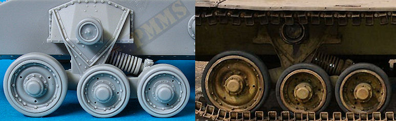
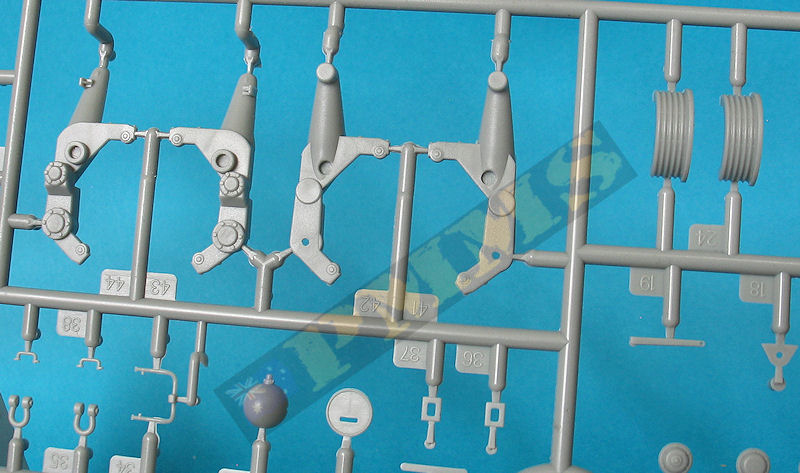
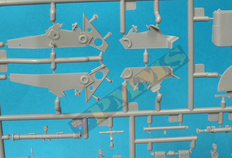
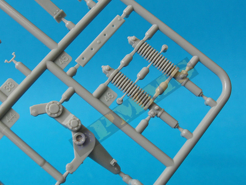
The main bogie mounting is well done with even rivet detail on the inside which you can't see when fitted to the hull as well as the mounting post for the return rollers. The main suspension arm that traps the large suspension spring and smaller wheel are designed to be movable but as the large wheel arm is fixed this results in only partial movement being possible. Added to this the location of the securing ring for the smaller wheel arm it's nearly impossible to glue without gluing to the arm as well and it's probably easier to glue the whole bogie unit together ensuring the road wheels all line up with the ground line.
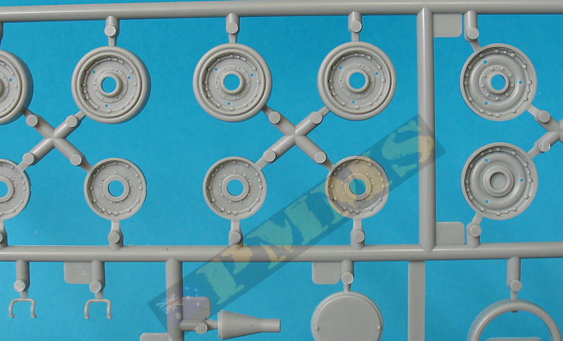
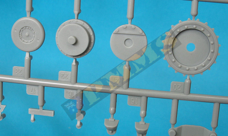
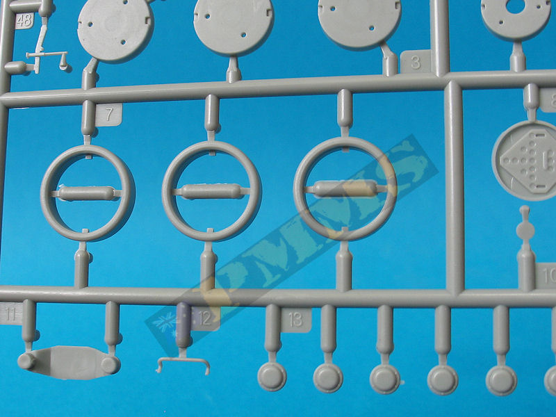
The road wheels have a different dish pattern from those in the Miniart Valentine kits and feature another of the five different road wheel patterns seen on Valentines. The rim and bolt head detail is well done as is the rim contours and the retaining hub but there is the wheel size issue as mentioned above that sees the road wheels slightly undersized.
The actual wheel measurements: the larger wheels are 24 inches in diameter including the rubber tyre. The smaller wheels are 19.5 inches in diameter including the rubber tyre. This equals 17.4mm (rounded) in 1:35 scale for the larger wheels including the rubber tyre and 14.5mm (rounded) in 1:35 scale for the smaller wheels including the rubber tyre give or take a fraction of a millimetre.
The kit wheels are 16.5mm for the larger wheels and 13.6mm for the smaller wheels give or take a fraction of a millimetre giving a difference of only 0.9mm for both wheels. Under normal circumstances any discrepancy under 1mm is really not worth bothering with but this issue here is where this discrepancy manifests itself. With each wheel being a little undersized when fitted to the bogies the extra space between the wheels results in a noticeably larger gap between the wheels than should be. But I guess it's up to the individual if this is a major issue or not considering the rest of the kit is spot on dimensionally as well as the level of detail included?
The seven part drive sprockets build into a nice representation of the unusual Valentine sprocket assembly with the large brake housing on the outside of the sprocket. The sprocket itself has the correct number of teeth and represents one of the two different sprocket styles I have seen in reference photos, this can also be made movable by securing the final drive pin through the sprocket with small cap (part B49) and given the larger size and open spaces of the sprocket this is not a problem and the movable sprocket comes in handy when fitting the track later.
At the front is the four part idler mounting that builds into a nicely detailed unit to which is added five small bolt heads provided either as etched bolt heads or plastic bolt heads moulded onto the C sprue runner. These have to be carefully cut off the sprue and you have to make sure each is cut the same height as there isn't any indication, for this reason I found it easier to use the etched bolt heads as these are all the same thickness just you have to use super glue to attach, no big deal.
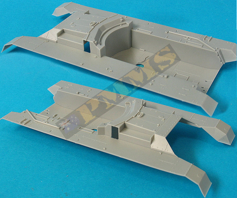
All the bogie/drive sprocket/idler sub-assemblies fit precisely to the hull tub without any problems.
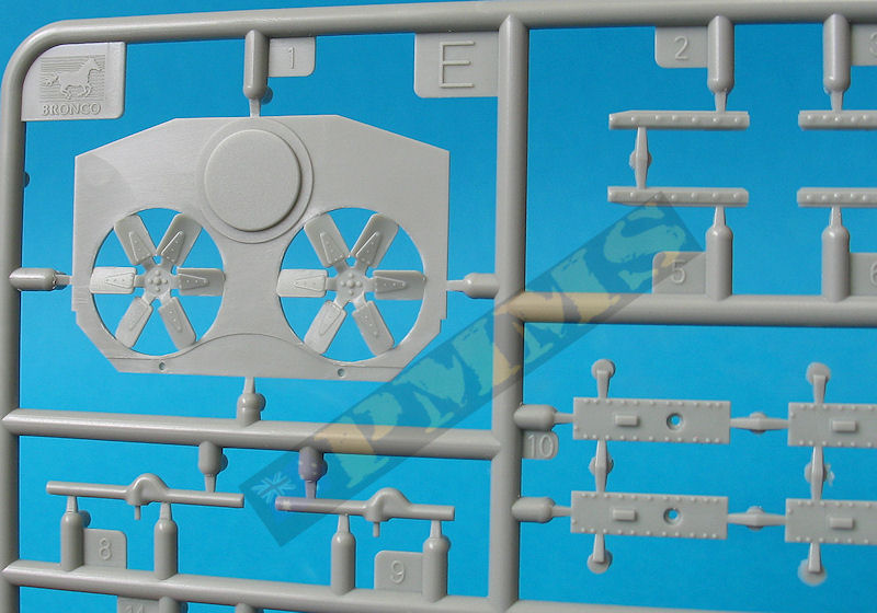
Inside the hull is the rear engine bulkhead with the two radiator fans with excellent definition moulded in along with fuel tanks and multi-part gearbox/transmission assemblies which fit into the hull tub perfectly. The only minor thing is to trim the ends of the mounting rods (parts E8, E9) fractionally to fit better between the sidewalls.
Mounted above these assemblies are the two large radiators made up of eight parts each with very subtle radiator mesh texturing. Don't bother using parts E42 and just glue all the parts, the assembled radiators fit precisely between the mounting rods and firewall without the need for glue allowing you to remove these if need be at any time.
On the engine deck is added the upper intake louvers with separate side panels and the edges of the louvers (parts C8, C9) needed to be trimmed slightly to allow the side panels to fit snugly, this being the only trimming needed in this area.
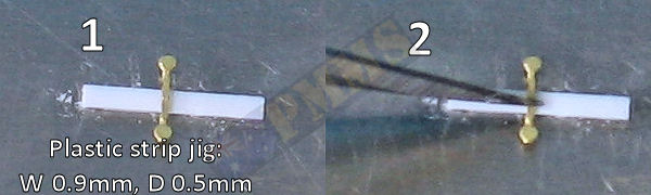
The upper rear plate again has excellent surface details with separate louvered access doors allowing you to position the doors open or closed to show off the inner details. Added to the doors are very small etched tie down cleats that need to be bent to the correct U shape and to facilitate this each cleat has two fine bend lines included on the underside but due to the size care is needed. I found it easiest to make a simple jig to aid in the bending process, see the guide here.
Firstly cut the tie downs from the etched fret, hold a steel ruler over the parts as you cut them away to avoid them distorting as they come away from the fret.
1. Make a jig by cutting a short length of 0.9mm x 0.5mm plastic strip and glue to a hard flat surface, I used the back of a steel ruler.
2. Place the tie down centrally over the jig and hold in place with the back of a #11 blade.
3. Use a pair of tweezers to press down as close as possible to both sides of the jig.
4. Use the back of another #11 blade to lightly press the bends into the jig sides to get a tight U shape, also ensure the round ends are sitting flat.
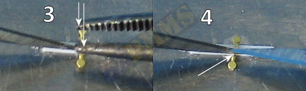
5. You now have a nicely formed tie down ready for fitting, simply repeat this for each tie down.
6. Using the tip of a #11 blade pick up the tie down, sounds easy but there is a knack to doing this. First the brass part must be on a hard surface and the #11 blade must me sharp, if you try this with a dull blade it will end in tears.
Press the tip of the blade onto the etched part just hard enough for it to "grip", not hard enough to cut the part or break the tip off the blade, practice may be needed to get this right?
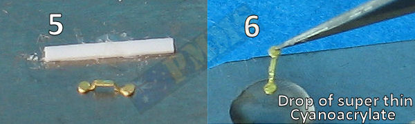
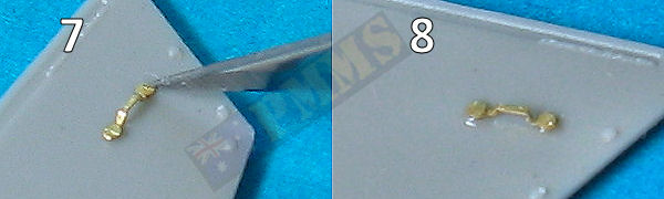
7. After picking up the brass part lightly dip this into a drop of super thin cyanoacrylate you put on a nonporous surface earlier (an old #11 blade works fine). By lightly I mean lightly, just touch the surface of the drop don't break through the surface or it can pull the brass part off the blade tip into the glue drop.
8. With a small dab of glue added to each end of the tie down add to the model in the required position, be sure to get this right as you don't get a chance to move it around as it sticks instantly. After placing this lightly press the other end of the tie down to make sure that is attached securely and there you have your tie down attached.
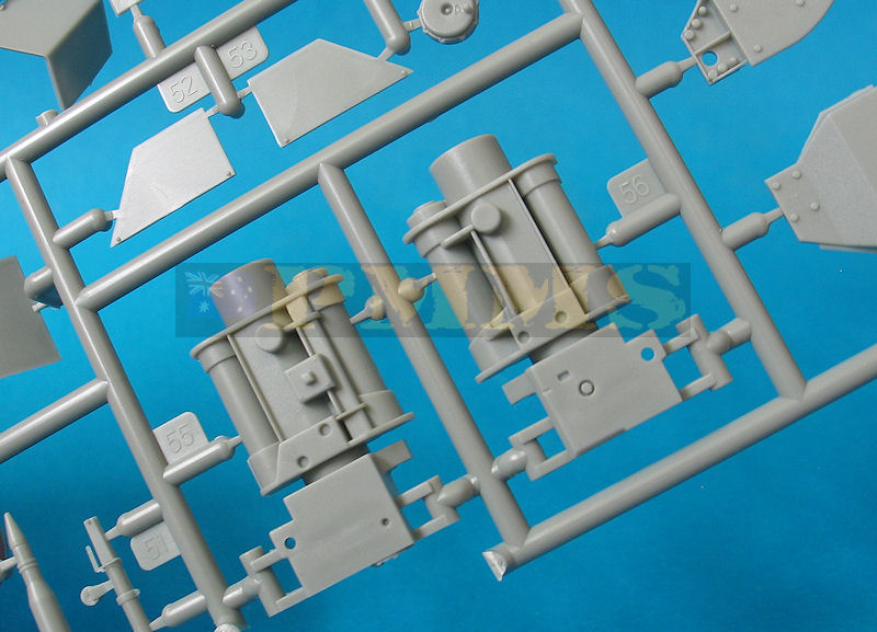
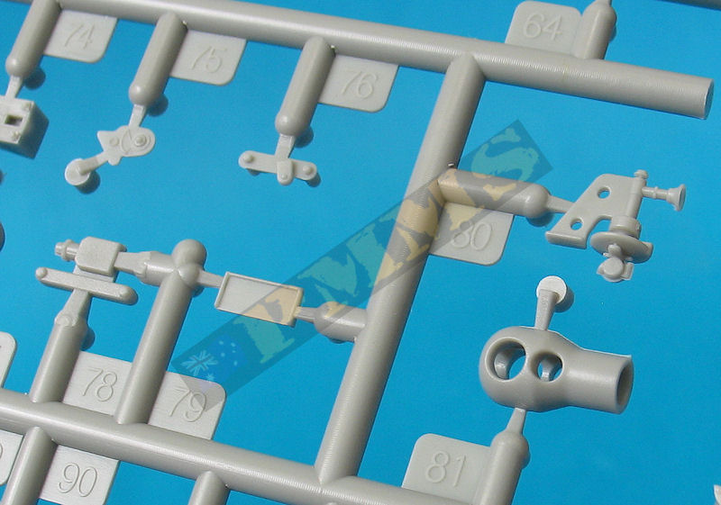
Also fitted to the rear plate are the two smoke generator units with thin brass brackets added with the fit of the plate to the upper hull being very good not requiring any trimming. Once the plate is attached the etched rear fender supports are added that do require care to get the angles of the bolted flanges correct but not difficult with a little test fitting before gluing.
On the vertical rear plate is added the large leaf spring towing rack for the late version only plus the towing brackets and tow hooks, note the brackets are different either side with the distinct step along the outer edge, this is supposed to be there so don't be tempted to shave flat thinking it's a huge mould slip.
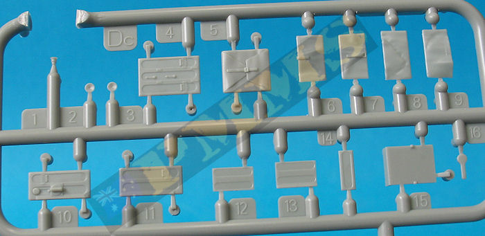
On the fenders are added the storage boxes with separate front panels but you will need to trim the insides of the box sidewalls as they are thicker at the top than at the bottom (so they will come out of the moulds) but the front panels won't fit properly unless you trim the walls to an even thickness, this applies to all four fender storage boxes.
Added to the rear most boxes are etched fender supports with smaller triangular brackets between these and the upper hull sides but the biggest dimensional discrepancy in the kit is with the left fender storage box and fender supports.
There is a large etched frame box (part P32) mounted to the rear of the left storage box (parts A10, A19), this box will require careful bending as not all bends have engraved bend lines so using a good etched bending tool is essential, anyway back to the dimensional issue.
The kit instructions have you attaching the etched fender support (part P1) to the end of the storage box along with the triangular support (part P3) like it is on the right fender but in fact the storage box should be 2mm shorter leaving a gap between it and the etched frame box. The fender support should actually be attached to the frame box and not the storage box. If you wanted to correct this you should shorten the storage box by 2mm and reposition the front latches evenly on the shortened box and fit the etched fender supports to the etched frame box.
But in reality this is not a ball breaker and leaving the parts as they come would probably go unnoticed apart from those like me that once you do know you have to fix it, oh the webs we weave etc.
The top of the storage box has moulded on tie down cleats which can be cut off and replaced with the etched tie downs if you wish, forming the cleats the same as above. There are other items added to the fenders such as the exhaust and head lights etc., but these are best left till the superstructure is attached so will come back to these later.
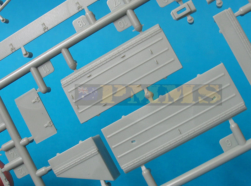
The full length sand guards are provided along with etched mounting brackets but in most instances these guards were removed by the crews when in action so these can easily be left off depending on a specific vehicle being modelled.
The parts all have bevelled edges and due to the high degree of engineering these fit together so well you would think they are a single piece once glued together, suffice to say no trimming or filler was needed.
Between these is the driver's station with the steering levers on the locker sides, the driver gets three foot pedals, central gear shift box, his seat and instrument panel attached to the inside of the front plate and all this can easily be seen after assembly.
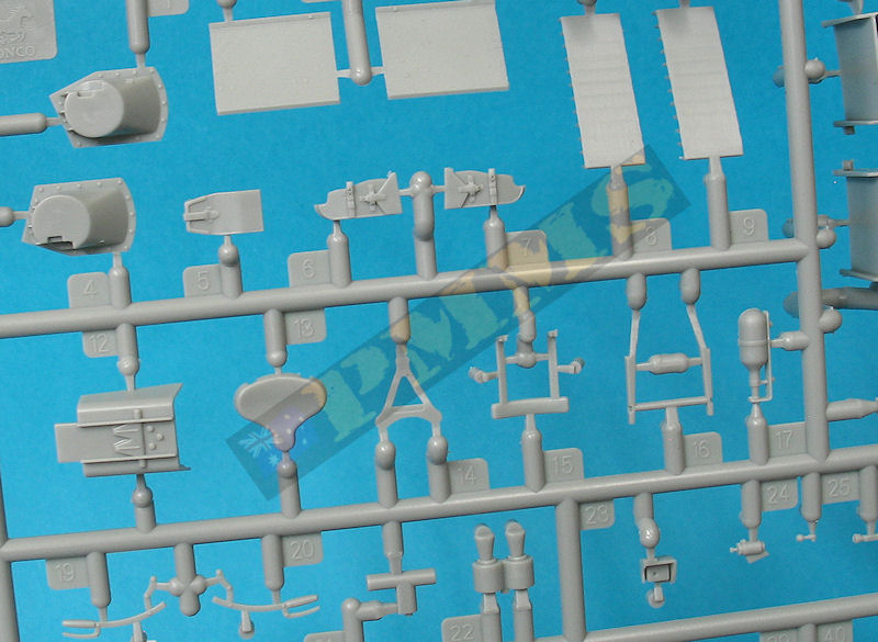
The left side bin carries 13 rounds of 76.2mm ammo with the top half of the shell casings provided along with two part etched lifting handles. The X bracket has two fine bending lines on the underside at the tip of each X and the outer most tip should be bent at right angles and the inner bent at 45 degrees for now. Once all four ends have been bent thus you sit the X on top of the shell casing and squeeze in the partly bent section securing the X bracket under the lip of the shell casing in the process, sounds so easy and it is really thanks to the bending lines. The D shaped handle should be bent at about 30 degrees to its base and then glued to the X bracket, all this should obviously be done before gluing the shell casings to the bins.
There are three other ammo bins, one with 7 rounds and two smaller ones with 3 rounds each, these small bins sit on top of the side sponson and you also get the lower section of the bin that sit outside the hull inboard of the suspension bogies, that's attention to detail. It's probably best to leave these outer bin sections off until the upper and lower hulls have been joined to avoid any alignment problems.
There is a small junction box and electrical ducting on the left side in front of the rear most ammo locker and this has a very fine etched guard cage (part P40) which does require extra care bending to shape and in fitting as it's very thin and fragile.
The Loader's and Radio Operator's seats have etched back supports and fit to the side sponsons, you should cut off the locating tabs on the seat brackets as these are way too big for the holes in the sponson but fit in place easily without them, so no big deal. The actual seats are designed to fold up on top of the sponsons when in action but these seats are fixed in the down position so a little surgery would be needed if building the kit in firing mode.
At the back of the compartment are a few additional items plus the gun traverse guide with fine teeth included for the traverse wheels on the gun mounting, these mate together later during the final gun assembly.
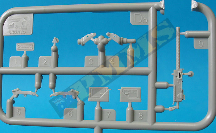
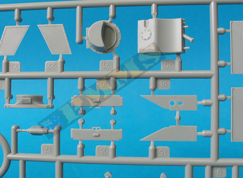
We now come to probably the standout feature of the fighting compartment, that being a superbly done Wireless Set No.18 that includes it's canvas cover either in the open or closed position. The closed cover is just a single piece but it seems a shame to hide the radio so the six part (4 plastic, 2 etched) expanded cover is carefully glued together and attached to the front of the radio box. The canvas sections have subtle contours included for added effect and if you wanted to be very picky thinning these down a little would improve the appearance even more.
The Wireless Set No.18 was the standard British Army Battalion radio set designed to be carried as a backpack by the operator and had a canvas cover for field operations with the kit radio including the backpack fittings in etched brass even though these can't be seen after the superstructure is fitted. The only omissions from the radio are the folding support arms for the front metal doors and added these from thin card or spare bits of brass will finish off the radio nicely.
Also included is a three part etched headphone set with two small plastic ear pieces and suffice to say this does require extreme care during assembly due to the small size and fragile nature of the etched parts. To aid in fitting the plastic ear pieces I drilled two small 1mm holes into each ear piece to sit the ends of the etched clip and the end result is worth the effort adding a nice finishing touch to the radio.
There is also a two part microphone with the handle and separate mouthpiece both in plastic and as the round mouthpiece is only about 1mm across advising care is a given, the only additions to the radio assembly were the headphone and microphone cables added from thin copper wire.
There is scope to add even more detail in the form of small brackets and bolts heads and other minor detail but all the main interior components have been represented extremely comprehensively.
There are some shallow pin ejector marks on the insides of the panels but all apart from about three are hidden when the separate items are added to the walls, those remaining visible are at the bottom of the side panels and easily removed with light #11 blade shaving.
All the inner wall equipment fits into place easily apart from the large tank on the left side (part G46) which had to be fitted about 1mm further up the wall than indicated, this required trimming of the tank side profile to fit the side panel contours in the new location. This move was needed to allow clearance for the tank over the ducting (part G18) when fitting the superstructure to the hull.
Another minor alteration was the location of the two nicely represented Sten Mk.II SMGs with etched attachments also on the left wall, these had to be moved higher up the wall as they fouled on the large ammo bin when fitted as indicated.
Everything on the right wall fitted as indicated as did the front plate detail along with the Driver's visor flap that can be fitted open or closed as required.
The small roof panel is really quite busy with two full pericopes made up of six plastic and one etched part each for an excellent appearance, the periscope bodies are provided in grey or clear plastic depending on your preferences.
The five moulded on tie down cleats can be replaced with the etched cleats if desired and there is a full width etched lip along with the rear edge that has to be bent to an L shape and as the lip is only about 1.5mm wide the use of a good etched bending tool will be needed to bend successfully.
The aerial mount for the radio is on the right side and there is also an intricate etched No.19 aerial mounting provided but this is not required for the No.18 radio used with the kit, another optional extra is a very well done M1919 cal .30 machine gun and pedestal mounting which was fitted to marking option 3 if you build this vehicle?
The cal .30 is very nicely detailed and will come in very handy for other purposes if not used here with the fit of the superstructure panels to themselves and to the hull being excellent again not requiring any trimming.
Once the superstructure is fitted to the hull there are numerous items added the superstructure sides and the fenders with everything fitting without any problems including the multi-part cable reel and search light on the right and the exhaust/muffler on the left fender. The only parts to be a little troublesome were the etched front fender supports (parts P52, P53) which have an odd angle between the fender and sloping front plate that needs a bit of trial and error to get correct.
Added to these supports are the two headlights that are different for the early or late versions so check the part numbers for the appropriate parts, the two small position lights with the etched guard also needs careful bending around the clear light. The large barrel cleaning rod container tube fitted to the front plate is about 1.5mm too short and should extend to the lower edge of the front plate as shown on the box art. If you fit the tube level with the lower edge the top will be further down the plate than it should but this may be a little less conspicuous than the bottom position?
There is a choice of fitting the steel tow cables or spare road wheels as storage depending on the vehicle option being built with different small brackets added to the superstructure sides so again fit the required parts for your model.
Mounted centrally on the front plate is a rack for four spare track links with two very fine wing nuts used on the support brackets, there are about 12 of these wing nuts on the sprue D runners which can be used as required to add detail. The instructions also have wiring diagrams for the front and rear lights for you to add these from thin wire or stretched sprue with small junction boxes also provided for the hull outlets.
There is also shown an option to add longer lengths of track to the front plate as additional armour for one of the marking options but the extra track is not included with a note advising to buy the separate Valentine track set #AB3536 if you want this option. So if you don't want to buy the extra track set just pick a different marking option, easy.
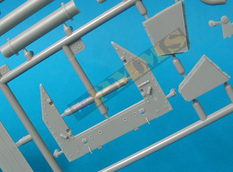
With the traverse assembly glue the two small wheels (D40, D41) together before fitting to the bracket (part C42), and after joining the mounting halves the Gunner's controls and seat with two small springs can be fitted to the left mounting without any problems. The mounting rear plate (part C59) has bevelled join edges as does the gun mounting sides and this results in a perfect and seamless fit of the rear plate.
Added to the rear plate is the spent shell collector box and this can be assembled in the stowed travel or extended firing position with alternate etched braces depending on the final arrangement? Note there are some shallow pin marks on the inside of the shell box that are visible in the extended position but these are easy to eliminate if needed.
The assembled gun mounting can be fitted into the fighting compartment by gluing the lower ball mounting into the hole in the compartment floor but make sure you don't glue the ball in the process if you want the gun to traverse? The traverse assembly on the front of the mounting rest against the traverse plate added to the hull earlier quite snugly allowing the gun to traverse but note there is only a small amount of traverse available for target aiming adjustments.
The breech/gun housing is made up of 14 plastic and six etched parts with the movable breech block trapped between the two breech halves with the only joins being along the top and bottom of the assembly but as the fit is good these are negligible in any case.
Also trapped between the breech halves is the lower block actuating bracket which moves in conjunction with the breech block and side mounted lever so make sure you don’t glue the bracket (part C92) or the lever (part C62) to the breech itself if you want this to be moveable?
You should ensure the mating surfaces of the two breech halves are smooth and there are some ejector pins inside the housing barrel recess that have to be removed to allow the barrel to fit properly, these are easily removed before joining the housing halves together. Note, you don't have to fit the barrel as you assembly the breech/gun housing as indicated in the instructions as the barrel tube will easily slip into place later providing you removed the ejector pins as mentioned. This will allow you to leave the barrel unglued should the usual suspects produce a metal barrel/muzzle brake for the kit making it easy to do the swap.
The main gun sight and mounting is simplified from the 17 pdr kit but still builds into a nicely detailed sub-assembly fitted to the side of the gun housing.
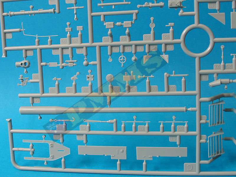
The barrel tube is in one single piece and apart from the fine mould lines to eliminate there is no other cleanup with rounded profile muzzle brake with the bore and side gas holes cleanly opened up. When fitting the barrel/muzzle brake to the gun you should ensure the gas holes are aligned correctly as there is no locating notch or similar on the breech end of the barrel to have the alignment right.
Added to the breech are the large gun guards either side and shell ejection guard at the back with these having large locating pins for a solid attachment, just watch if you want the breech block handle to move after adding the guards you will have to trim some off the small L fitting on top of the right side guard (part C94).
The assembled gun simply slips into the two locating lugs inside the gun mounting for a quick and easy fit, this also allows you to add the gun at any time for easier painting. There is a separate travel lock bar (part C88) if you wish to fix the gun in travel mode or you can leave it free to elevate.
Added to the inside of the shield are five of those small etched tie down cleats and two other small etches brackets along with a another periscope sight and a fine plastic channel. On the outside are two fine plastic channels along to lower shield lip and you need care when removing these from the sprues as there are a couple of cut-outs in the channels creating weak points if the parts are handled roughly.
There are some very small etched parts and the periscope door added to the shield roof and the assembled shield is attached to the front of the gun mountings, note the gun has to be fitted before the gun shield as it won't go with the shield in place without a lot of cursing.
Overall the fit of the major parts such as the upper and lower hulls, superstructure to upper hull and gun assembly was excellent without any trimming or filler needed, I was able to assembly the review kit with all the major sub-assemblies unglued to allow the parts to be added or removed for photo taking and they just slipped together effortlessly.
The only minor trimming was on some of the smaller parts as mentioned above but no filler was required anywhere, testament to the excellent engineering of the kit overall.
Note; Option 1 and 2 are the same vehicle in different colours but the period 'Italy 1943' is not possible as the Archer was not produced until 1944.
| Option 1:
Polish 7th Anti-Tank Regiment, 2nd Armoured Brigade, Italy 1943  Option 2: Polish 7th Anti-Tank Regiment, 2nd Armoured Brigade, Italy 1943 Option 3: 3rd Anti-Tank Regiment, Royal Canadian Artillery, 3rd Canadian Infantry Division (AOS 46)  Option 4: 15th Scottish Division, NW Europe, winter 1944-45  |
 |
Clearly this kit is not for the inexperienced modeller due to the sheer number of small parts both plastic and etched but there is no real area of assembly other than this that should be too much. The final result if you put in the work along the way is exceptional and after waiting so long for a decent 'Archer' kit this effort from Bronco should make every Allied modeller smile, a lot.
Rating 9.5/10
I have indicated I feel this kit is entitled to the tag '2010 Kit of the Year' for as well as the reasons mentioned above the 'Archer' also looks just damn sexy. But of course this is purely subjective because if you are not into Allied armour or British armour more specifically then you will be saying WTF?
Click on thumbnails for larger view
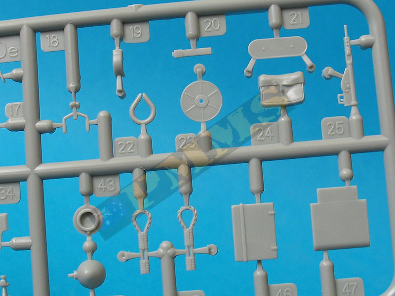
Sprues


Sprue detail images


Detail and Assembly images
![]()
| Valentine Tank Power Vol.XC Wydawnictwo Militaria 331 ISBN: 9788372193315  |
Valentine Tank Walk Around Squadron Signal Publications ISBN: 978-0-89747-621-8  |
 for
the review kit.
for
the review kit. 