
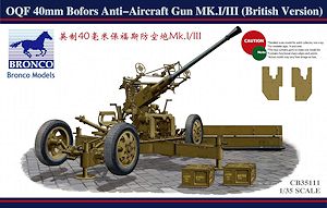
OQF 40mm Bofors Anti-Aircraft Gun Mk.I/II (British Army)
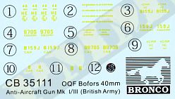
Bronco Models 1:35 Scale Kit No. CB-35111
Review by Terry Ashley
Kits with the revised parts will have a "Tooling revised" sticker added to the box top so you will know the revised carriage is included.
For those who have bought the initial kits with the problem carriage you can contact Bronco Models via their service mail box of Bronco@vip.163.com or contact your place of purchase for a replacement part.
Bronco Models also apologize to the modellers who already bought the kit for the inconvenience caused.
The 40mm Bofors L/60 light anti-aircraft automatic gun was developed by Bofors of Sweden initially for Naval use and used extensively by many Navies during and long after WWII. It was adopted by the British Army in 1938 and by the U.S. Army in 1941 as the M1/M2 and was also used extensively by other nations including Germany who captured many during the Polish and French campaigns.
The Bofors was also used extensively buy other Allied Armies most notably Canada who produced the majority of WWII guns as well as by the Australian Army and just about every Allied country involved in WWII for that matter.
Originally mounted on a four wheel trailer, later versions were on a two wheel trailer for airborne use as well as self propelled versions as local modifications (North Africa for example) and purpose built vehicles such as the Crusader AA.
After WWII the Bofors was further developed as the L/70 and used by many nations as both Naval and Army types right up to present day with the 40mm Bofors being one of the longest serving artillery weapons produced.
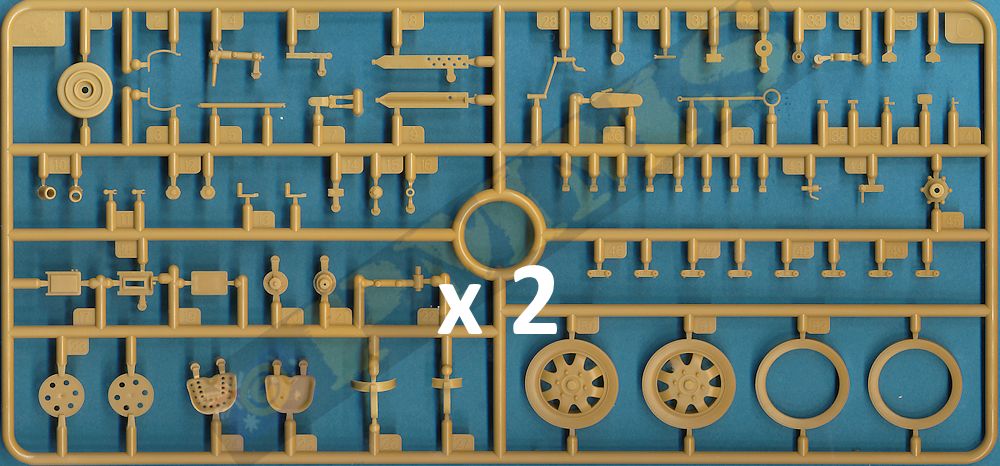
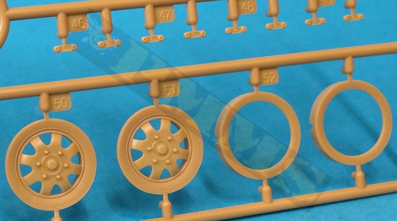
The main difference from the previous kit is the inclusion of the British riveted carriage and wheels with the eight cut-outs around the rims there is again the choice of manual or electric control types along with the early double ring sights or the later British-designed Stiffkey sight introduced during 1943. There are also other smaller details such as redesigned receiver and barrel assembly and the kit can be built with or without the shields fitted.
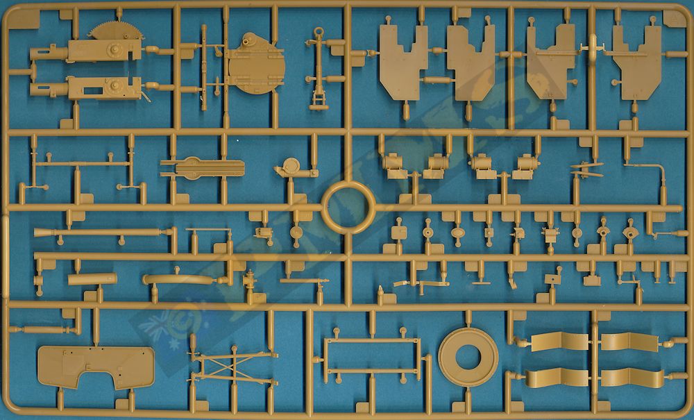
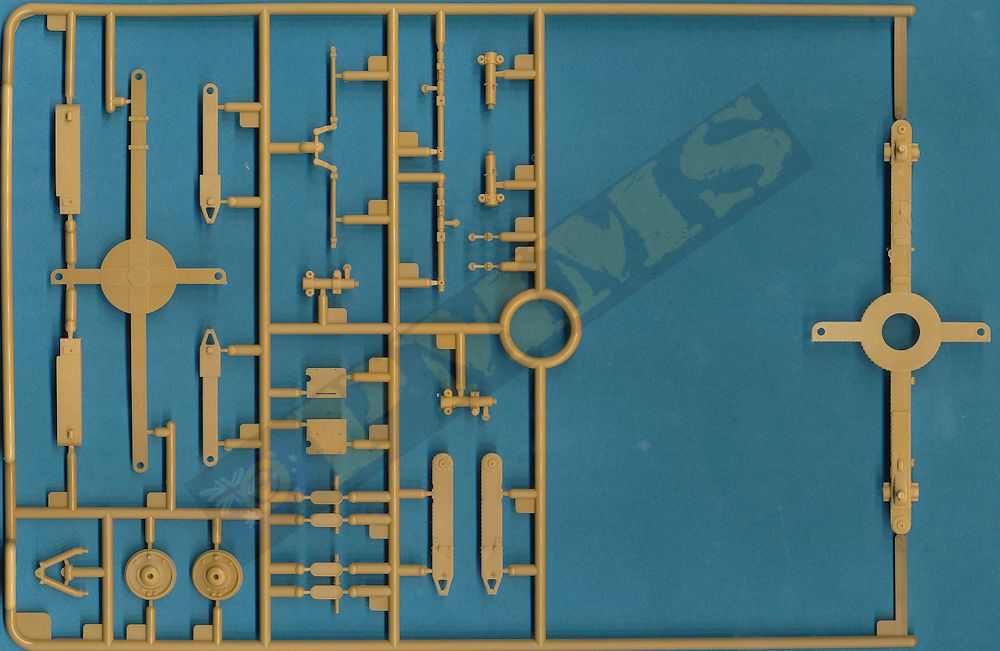
The kit has three new sprues (A, B & C) along with sprues (D, F, H) from the previous kit with some D & F parts marked as not used so you need to ensure you use the correct parts for this kit. The kit consists of 326 parts in beige plastic, 18 small wing nuts in light grey plastic, 1 metal spring, 66 etched parts plus the decal and instruction sheets.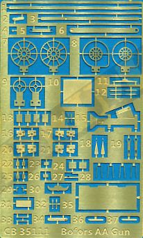
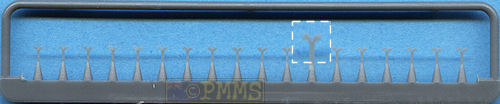
Plastic wing nuts
While not having any available 1:35 plans the kit matches available data well and the level of detail included matches reference photos of the actual gun very well which all makes for a good start. I’ll have to leave any dimensional issues till more detailed info is available.
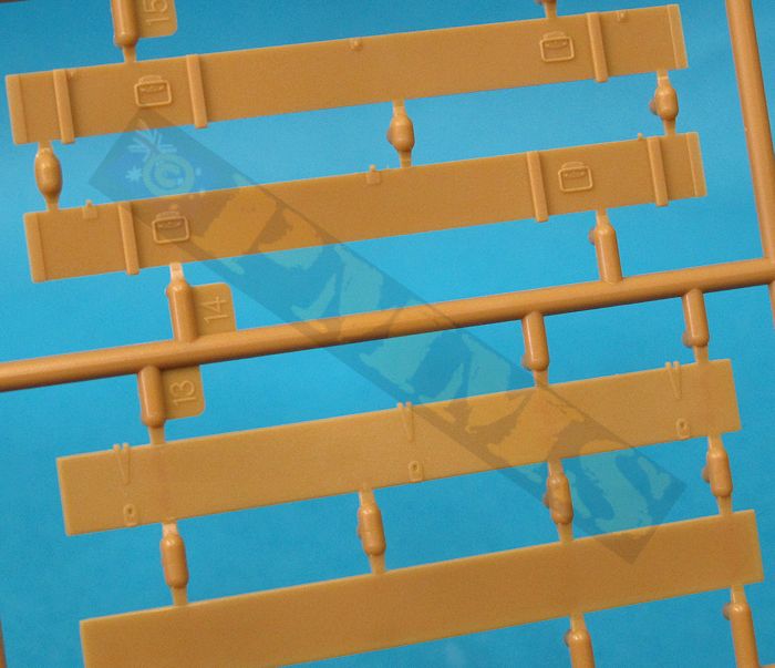
The moulding quality is very well done with clean crisp mouldings and detail such as moulded on data panels and the many rivets on the carriage. Other surface details of bolt heads etc are also finely done with no pin marks evident on the parts and just the usual moulding seams to be removed. This needs some care on the very small parts and the larger finely moulded parts like the ribs on the Stiffkey sight, due to the finesse of some parts there is the odd minor flash but this is a bare minimum with the majority of parts cleanly moulded.
As with the previous kit any of the sprue attachments are laid over the part mating surface and not the actual part which makes the clean-up easier without compromising the detail but again take care with the small parts as the attachment but is quite prominent in relation to the size of the part.
One word of caution with the many small plastic and etched parts in the kit and that is to work well over your work bench as the dreaded carpet monster is waiting for you to dare drop any parts during assembly.
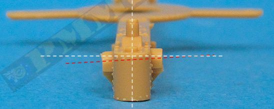
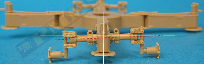
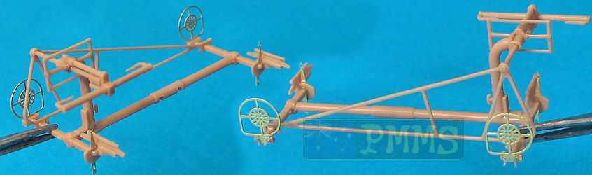
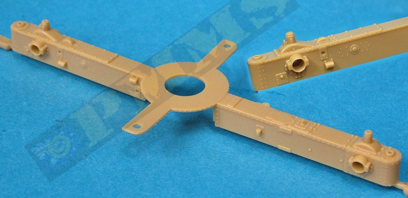
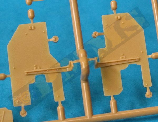
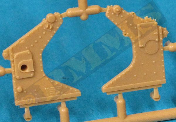
I initially thought the carriage legs may have been twisted but this wasn’t the case and on checking two other kits the same issue was found and is quite disconcerting. About the only thing that can be done is to carefully cut away the mounting collar from the “high” side of the carriage leg and reposition slightly lower parallel to the mounting collar on the opposite side. The hole for the suspension arm will also need to be altered to align parallel with the other mounting collar, this is no easy task given the collar mounting plate is very thin and there are also other rivets close by that may be damaged in the process.
This prevents the wheels from sitting evenly on the ground and will require a fair amount of work to rectify.
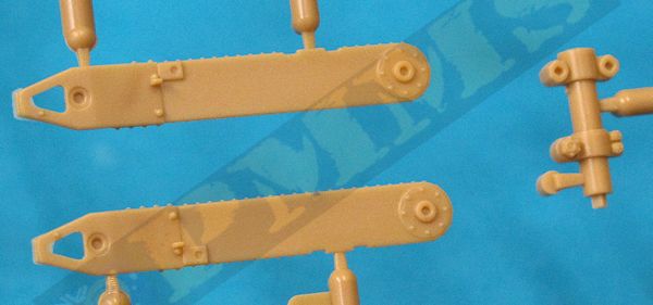
The two suspension arms (parts B4, B17 and B7, B8) on either end of the carriage legs have to be inserted through the mounting collars on the side of the carriage while slipping the inner ratchet (parts A29, A30) inside the carriage leg and then glue together without getting glue on the carriage itself if you want the suspension arms to be movable (step 16). This is far easier said than done as there is very little if any clearance between the parts to be glued and carriage and it may be easier to decide if you want the wheels raised or lowered on the finished model and simply glue the arms in place. If you decide to glue the arms in place it may also be easier to wait until you have assembled the other suspension linkages and axles to the arms to make sure you glue the whole assembly at the correct angle to the carriage, in all this area is probably the trickiest of the kit compounded by the issue with the suspension arm angles.
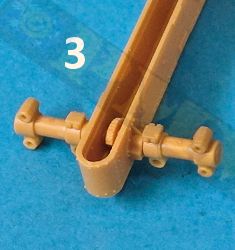
As I needed to have the arms rotatable to show the alternate positions for the review I modified the suspension arms to make this a lot easier and more robust but this isn’t really necessary for normal kit construction unless you plan on altering the position of the wheels on the finished kit.
I simple cut away the small locating lugs on the suspension arms, drilled holes into the arms and glued a length of 1mm plastic rod into one arm (step 1), then fed this through the carriage leg and inner ratchet (also with drilled out hole) (step 2) and then glued the other arm onto the exposed length of plastic rod (step 3). This made the assembly easier and gave a robust assembly to allow the position of the axles/wheels to be altered easily for the review images.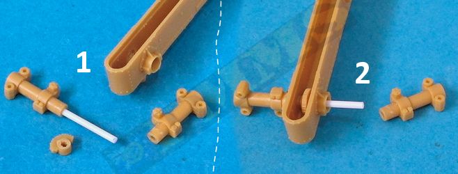
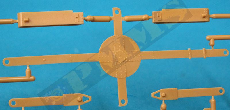
The remainder of the carriage body fits nicely, the four central curved sides have no gaps or trimming needed although there are join seams around the bottom panel but as these can’t be seen being under the carriage are probably not worth bothering with. The central gun mounting disc is added but you need to smooth out some raised pin marks on the underside to allow this to sit flush with the carriage base.
Fitting the suspension braces and axle posts to the assembled arms needs care as there are four differently numbered braces and you need to take care to fit these in the correct position although the differences between the parts is very minor.
On the end of the carriage legs are the cylinders for the extendable round feet and these have separate crank handles that can be shown folded or extended when in use. There are numerous smaller plastic and etched details added to the carriage arms and care is needed due to the small size of some of these along with the stakes stowed in the travel position. One thing to watch in step 24 is the fitting of small lifting handles made up of etched parts P12,P14 and plastic parts A45, the instructions show to fit these in the wrong place on the small hump on the carriage leg when they should actually be fitted to the sides of the central post as shown in the illustration in step 25.
The outrigger arms also have nice rivet detail with separate top and bottom plates that trap the main carriage between them when fitted allowing the outriggers to fold for either the firing or travel configurations. The end support feet cylinders and smaller detail are added as with the main legs.
The large towing hook assembly attached to the “front” axle assembly is made up of 6 parts and they all need to be held together with the small brackets (parts C7) so all can move after you have glued the two small brackets together, this is so the two outside braces (parts B16, B17) can be moved to be positioned correctly onto the axle assembly. After you have glued the towing hook assembly to the axle assembly only the main tow arm (part A4) will be movable but as mentioned the other parts must be free to move beforehand so they can be aligned correctly.
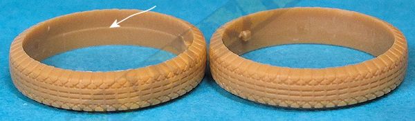
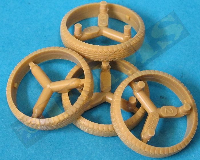
as per right tyre image.
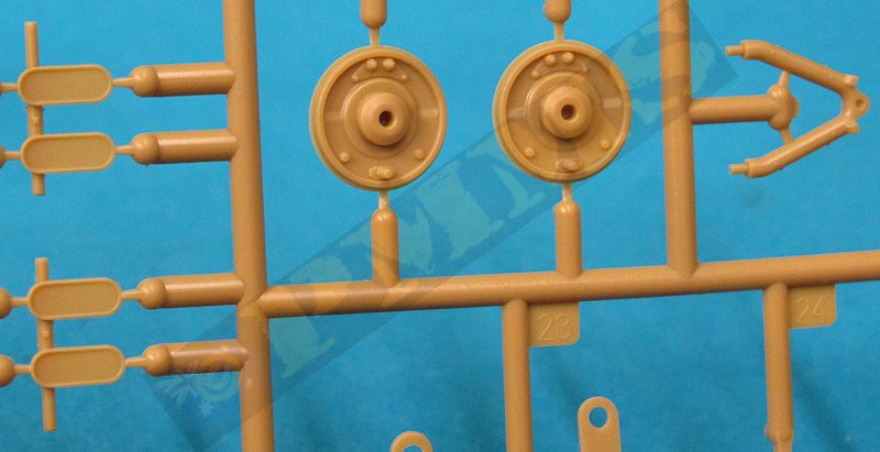
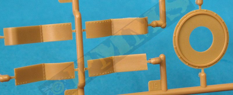
Inside the rear wheels are three part brake drums and if you want the wheels to rotate after assembly the front section of the drum is held in place with a small collar (part C32) glued to the pin going through the rear drum part, but you will need the reduce the diameter of the collar a bit to allow proper clearance in the rear drum recess for this to rotate freely. The assembled brake drum is then glued inside the wheel rim and in turn glued to the axle stub with the wheel free to rotate.
On the front wheels there is the mounting cylinder (part C45) through which slips the axle that is held in place with another small collar (part C16) and you must glue this collar to the axle stub without getting glue on the mounting cylinder if you want the wheels to rotate? The cylinder is then glued into the wheel rim making sure you don’t get glue on the axle or collar in the process, this is a little tricky but if you didn’t want the wheels to rotate after assembly both the front and rear wheel assemblies can just be glued to the respective axles for a fare quicker and easier assembly.
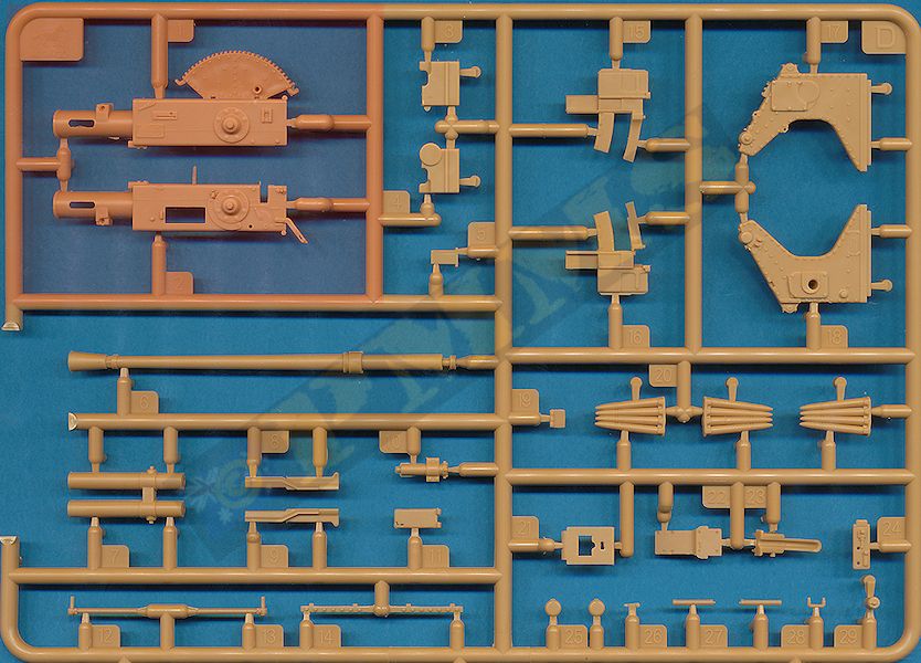
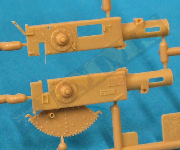
The elevating arc is included on the right half; this has rivet detail on both sides free of pin marks as well as the elevation teeth very well defined. The detail on the breech casing assembly is very well done with data panels and well-defined trunnion mountings on both sides with separate side and top covers and openings in the recuperator spring cover.
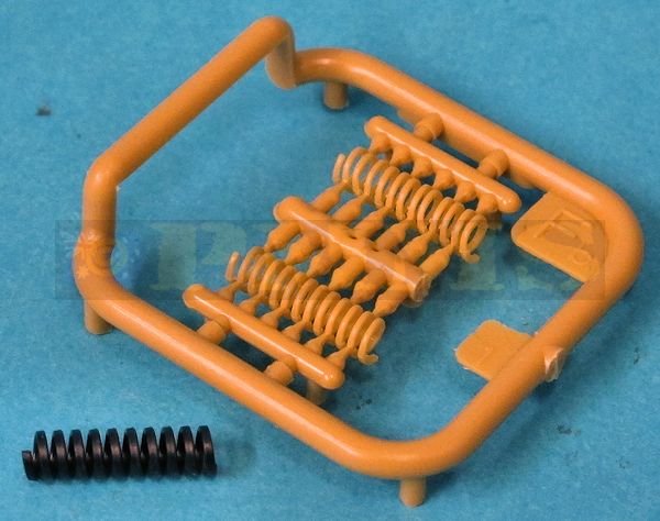
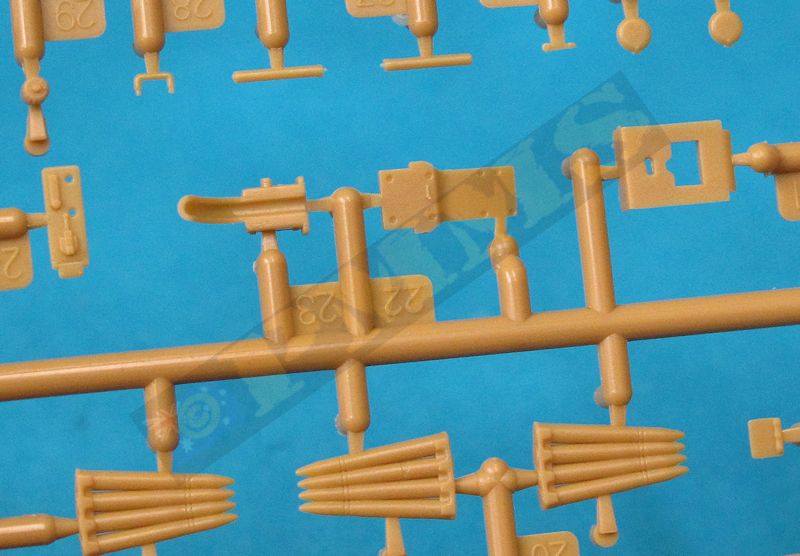
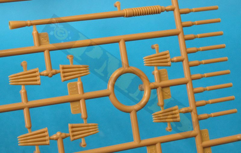
The barrel tube is now in three pieces with the tube and fully hollowed out flash hider in one part, the barrel collar and inside tube section with the moulding seam on the barrel tube the only clean-up. Added to the inner barrel tube is the recuperator spring which is provided as an actual metal spring or in impressively moulded plastic spring, this does need some care removing from the sprue and cleaning up the attachment burs due to it being rather “springy” as you might expect. The plastic spring is slightly thinner than the metal one and your choice of spring fits over the rear barrel tube with theis trapped between the two part gun breech.
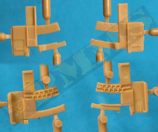
At the back are the full automatic loader assembly in six parts that includes the lower automatic loading tray and again the detail on the parts very well done including the inner feed pawl on the left and right loading frame. These and the rear cover also have excellent flush screw detail included and added under the recuperator spring housing is the recoil cylinder in two parts.
The barrel/breech and automatic loader are trapped between the breech casing assembly halves on small inside guides as the halves are glued together and the instructions indicated the whole barrel/breech will recoil using the spring. But his is quite impractical really and it better to just glue the assembly together to ensure the top and bottom join seam was as small as possible and the barrel sits the correct distance from the front of the casing.
Added to the assembled gun is the top and side covers, you could leave these open to show the inner detail in a diorama setting with the gun undergoing maintenance if you wished? Other details include two underside bolt strips and the left side hand operating lever. Also provided is a 4 round ammo clip to add inside the auto feed should you want and the fit is perfect with the clip held snugly in place without the need for glue.
The kit also includes the automatic loader hood should you wish to use this but note these hoods are usually only fitted when the gun is in the transport mode.
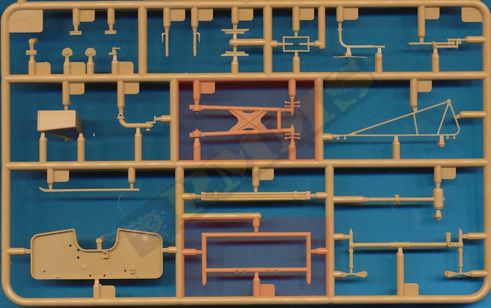
The two equilibrator cases and their joining trunnion bracket are moulded as one piece with just separate end caps and this eliminates any unsightly join seam with just the fine mould seam to remove. The two pistons fit inside the cases and join to the sides of the elevating arc but it’s best to leave these off until the gun is mounted between the two carriage frames later.
Amongst the delicate sub-assemblies with the kit are the large sights mounted on the front of the gun housing with two types provided in the kit. There are the initial double ring sights or the intricate Stiffkey sight and as mentioned above with the double ring sights being the easiest to assemble and most appropriate to use for early BEF or 8th Army Africa guns as the Stiffkey sight was not introduced until 1943.
The double ring sight has the one piece ‘H’ tube frame with the four etched ring sights added front and rear, with the larger ones at the front obviously. Added to each of the etched sights are two of the small wing nuts provided and I found it best to drill small 0.45mm holes into the plastic sight mounts and insert the wing nut shaft into the hole. The etched sight already has 0.45mm holes included for the wing nuts so you use these as a guide to drill into the plastic after attaching the sights with cyanoacrylate, ensure you firmly hold the plastic frame with tweezers while drilling or there could be problems.
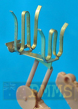
The Stiffkey sight is a different proposition as it is made up of 17 fine plastic and 7 very small etched parts with the cleanup of the fine moulding seams on parts F8 and F14 in particular requiring extreme care not to damage the very fine mouldings. Part F14 the large triangular frame must be about as fine you could mould something in plastic and it’s probably best to clean up the mould seams while the part is still attached to the sprue for a bit more support.
Assembling the sight is fairly straightforward really providing you take your time to ensure the right part goes in the right place and allow time for the glue on one part to ‘go off’ before attaching the next. The only adjustment required was to enlarge the locating holes in part F10 for the pins on part F8 for a better fit but other than that everything fitted nicely which did ease some of the pain with so many small and delicate parts.
Once assembled you again have to handle this with care and it’s definitely a case for leaving this off until the very last to avoid damage, but the finesse of this sub-assembly sort of sums up the quality of the whole kit providing you take your time.
The delicate Stiffkey sight with 17 plastic and 7 etched parts requiring some care during assembly
The two 4 round ammo clips in brass quite an intricate assembly made up of seven etched brass parts and two plastic mounting posts with the two long brass strips (parts P1, P3) for the W brackets having to be bent to shape.
Unfortunately for some reason Bronco don’t give you the jig for bending the W brackets with this kit as they did with the previous kit and this does make bending these racks to shape a whole lot harder, if you have the first Canadian Bofors kit you can of course use the jig from that kit. It’s best not to anneal the brass beforehand as you want this strong enough to hold the ammo clips once bent to shape.
Soldering the W brackets to the base stubs is easier than it sounds by holding the W brackets inverted in a small clamp, reversible tweezers or “spare” hands which ever you prefer and with a pair of tweezers hold the base plate in position over the W brackets ready solder. Add a small amount of flux and the smallest chunk of solder on the join and then apply the heated soldering iron, not to the solder itself but just touch the brass near the join and the heat will melt the solder which will run between the bracket and stub to form the join.
Repeat for the other three joins and provided you hold the base plate in the precise position as you apply the iron tip there shouldn’t be any problems, not actually touching the join with the iron tip also prevents this moving as you apply the heat. Just remember to use the smallest chunk of solder to avoid excess, I sliced a small sliver off 1mm rod solder and then cut that in half again, that is all the solder needed for such a small join.
The two plastic support rods have to be then attached using cyanoacrylate and these are then glued to the small attachment lugs on top of the right carriage trunnion, you may want to leave this assembly off until final assembly to avoid any damage as it to sticks up asking to be broken off in the meantime.
The 4 round ammo clips provided fit perfectly into the W brackets thanks to the jig provided to get the shape right in the first place.
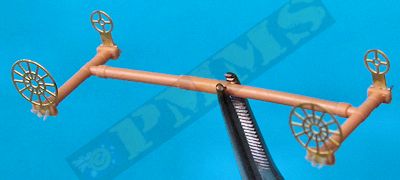
The kit gives a choice of the electric control version with the two electric motors added either side of the gun mounting or the manual control version with the side mounted hand wheels, as with the sights if building and early war BEF of Africa version of the gun these would be best built with the manual controls as the electric controls were not introduced till later. Also while the kit includes the electric motors it doesn’t include the large electrical distribution box mounted centrally over the tunnel that came with the Canadian Bofors kit so again it’s probably best to build the kit as the manual control version leaving off the electric motors altogether.
A pair of foot rests is added to the front of the platform frame and these are the early style without the small lever added for the electric control version. On the rear platform is a small azimuth indicatorgauge with a small decal provided for the dial face (not indicated in the instructions) but take care as there is no locating point indicated for adding the gauge to the platform.
The traverse gear is an extremely delicate sub-assembly made up of seven plastic and one etched part and the two parts (B5, B6) that make up the mounting post fit together well but are extremely thin at the joins require care when gluing together and handling afterwards. The level of detail obtained due to the multi part assembly is extremely good and the delicate nature of the assembly is a small price to pay but due care is needed.
The kit gives a choice of two styles of crew seats, the early type with perforated seat pan and the later style solid pan and wrap around back rest and again if building and early war gun the perforated seats would be the best option.
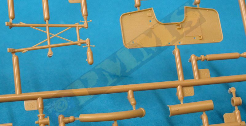
Finally there are the optional shields made up of four parts, two per side to reflect the spaced shields with the rear section including the upper mounting frames. The shields have the inside edges bevelled sharply to a thin edge while the middle is somewhat thicker but there is still a gap between the shields. The locating pins also simulate the shield bolts with the overall effect giving a good visual representation of the spaced shields from most angles.
The shields are attached to the platform frame by way of two long and two short supports and you can easily add the shields at any time or leave them off depending on your choice as not all guns had them fitted. The shields are prime candidates for etched replacements for a uniform thickness spaced shields as there is not a lot else that needs replacing with the inevitable update set given the quality of the kit as it comes.
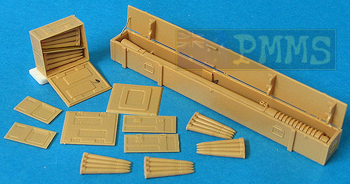
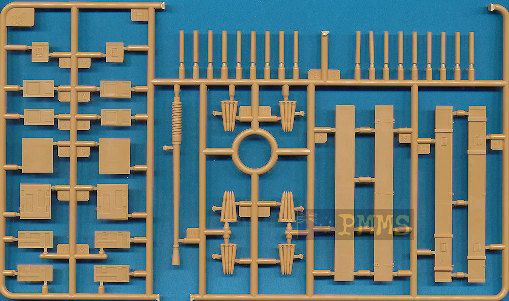
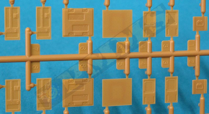
Detail on the stamped metal ammo boxes is very well done with the outer indentations reproduced as raised on the inside of the box sides and top which gives a very good impression when they are shown open.
The instructions indicate to add multiple ammo clips to the boxes but it would be better to add a spacer from plastic card and just use the top clip thereby leaving you spares to use with a crew or just add to a diorama setting.
The spare barrel box also assembles easily with the full spare barrel provided to fill the box should you wish to leave this open also? The barrel includes fully hollowed out flash hider as with the main barrel as well as the recuperator spring and fine threading on the breech end.
Some of the assembly sequences are quite involved due to the many small plastic and etched parts meaning you should be especially clear on what goes where by thoroughly studying the assembly sequences before doing anything.
But overall the instructions are very good and there shouldn’t be any major problems during assembly if due care is taken.
The gun is shown in overall olive drab.
|
Due to the complexity of some sub-assemblies (ammo rack and Stiffkey sight for example) with some requiring soldering and the finesse of the many small parts this may limit the appeal to more experienced modellers as some young and less experienced may encounter problems during assembly if not careful.
Rating 7.5/10
P.S. I have bought the issues with this kit to the attention of Bronco Models.
Click on thumbnails for larger view
Detail Images
Sprue detail images


Click Browsers BACK button to return to page
| Bofors 40mm WWII AA Gun in detail Wings & Wheels Publications R 058  |
| WWII US War Department Technical Manual CD-ROM TM9-252 40mm Anti-aircraft
Gun (Bofors) Easy 1 Productions #T006  |
Thanks to Bronco Models for providing the review kit.
