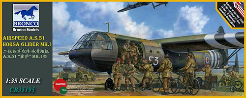
Airspeed A.S.51 Horsa Glider Mk.I
Bronco Models 1:35 Scale Kit No. CB35195
Review by Terry Ashley
Part 1 the Kit.

Just aft of the pilot's compartment on the port side was the hinged freight loading door that doubled as a loading ramp. 15 troops could be accommodated (or up to 30 on some operations) on benches along the sides of the main compartment with another access door on the starboard side. The fuselage joint at the rear of the main section could be broken on landing to assist in rapid unloading of troops and equipment and additionally three supply containers could be fitted each side under the centre wing section. Alternatively the Horsa could carry a single Jeep or a 6 Pounder Anti-Tank gun.
Horsas were used operationally in the Invasion of Sicily and Battle of Normandy as well as notable operations after the Normandy landings such as Operation Deadstick capturing the Pegasus Bridge and for Operation Dragoon and Operation Market Garden, both in 1944. The final operation for the Horsa was Operation Varsity in March 1945 carrying soldiers of the 6th Airborne Division across the Rhine.
The kit is broken down into sections with the main fuselage, rear tail section, mid wing and outer wings separate, these sections, the tail and the outer wings will be included in the just announced AB3574 Horsa Glider Wings & Rear Fuselage (Tail Unit) Set for those wishing to incorporate just part of the landed Horsa in a diorama setting. The kit can be built in sub-assemblies much like the real thing and be brought together to make the final glider or left separate either in a diorama or for display purposes.
No additional equipment or stores is included with the kit but Bronco already have an impressive catalogue of Airborne subjects that could be used such as the Airborne Jeep (kit CB35169, CB35170), Airborne 6pdr A/T Gun (kit CB35168, CB 35170), Airborne 75mm Pack Howitzer (kit CB35163), Figures (kit CB35177, CB35192) and Equipment (kit AB3567) sets so you can choose whatever load-out you wish for the kit.
The kit consists of 20 plastic sprue runners with:279 Parts in light grey plastic
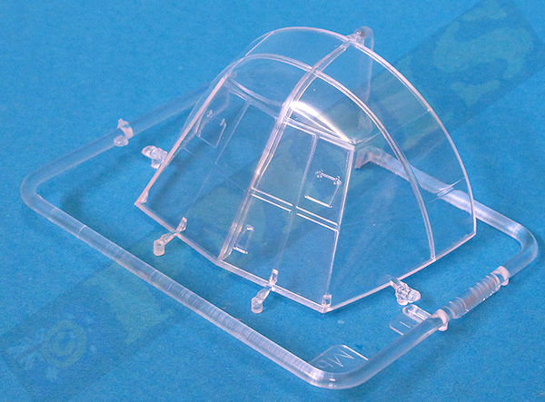
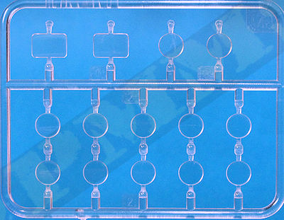
16 Parts in clear plastic
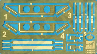
11 PE parts
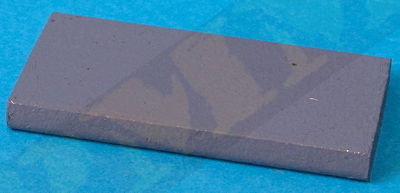
1 Metal nose weight block
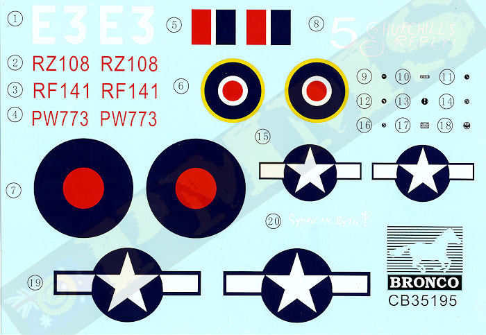
1 Decal sheet
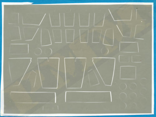
1 Mask sheet for canopy
1 x 15 page instruction booklet
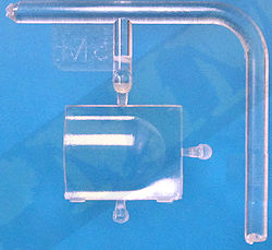
Clear parts
Metal nose weight block
The standard of moulding is very good overall with the usual mould lines and excess plastic nodes common to kits these days, the parts are relatively free of pin parks or flash although there is some very fine flash on a few of the larger parts such as the wings edges that is easy to remove with a pass of a #11 blade and some of the fuselage bulkheads have shallow pin parks as well as some that are slightly raised making them easy to remove, you also need to make sure the larger mating surfaces are perfectly smooth to get the best fit.
Your need to take care as there are quite a few small delicate parts as well as the larger wings parts and care is needed removing these smaller parts from the sprues and during assembly. The kit also includes some PE and canopy masks for painting as well as a large 73g metal block to use as a nose weight to keep it sitting nose down on the tricycle undercarriage, plus the large decal sheet includes 3 marking options all for the Normandy landings in June 1944, 2 RAF and 1 USAAF
The two seats have separate cushions with moulded on belts along with the control columns, the control wheels have two very small wing nuts to add in the centre and these will need care using. The pilot foot pedals are separate as well as central console with the Elevator Trim Tab wheel (part C13), the two Air Brake control levers (parts F10, F18), Compass (part C12) as well as the Tow release control lever (part C26), Undercarriage jettison control lever and Flaps control lever (part C21) although these levers are a bit on the thick side and could be improved using thinner card of etched brass for the levers (something for the aftermarket people no doubt?)
The three large compressed air bottles are included, two on the starboard side and one forward but the small switch but the small switch panel (with switches and the fuse box) on the port sidewall is not included, as well as the battery box and signal cartridge stowage panel are also not included alongside the port pilot seat, these items can easily be made from thin plastic card to complete the cockpit layout.
The large cockpit glazing is moulded as one large part and is very clear and includes the two clear vision panels in the closed position. You get a set of paint masks for both the inside and outside of the canopy to aid in painting with the cockpit trapped between the two front nose halves to complete the sub-assembly.
The inside floor sections in two parts are moulded commendably thin and have walkway ridges included with the bulkheads fitting around the floor sections, you have to pay very careful attention as to where exactly the bulkheads fit as some of the location is a little confusing in the instructions so make sure and test fit first comparing the bulkhead position and orientation to the illustrations before gluing. It could be an idea to mark the part numbers with a fine felt pen as you remove them from the sprues as some look similar but need to be in the correct positions.
The large top stringers have smaller attachment fillets added and you have a choice of adding the troop seats or leaving them out if you wish to load up larger equipment such as a Jeep, the seat locating holes are open in the rear floor section but not in the forward floor section and you will need to drill out the seat locating holes here if using the seats, something the instructions don’t show to do unfortuately? The seats themselves have moulded on seat belts and separate perforated end brackets plus the support legs to give a good appearance overall.
The side panels have the windows as small separate frames with clear port windows and the nose wheel is added under the front underside panel. The large cargo loading door on the port side has a separate smaller troop door that allows you to have the main door closed and just the troop door open or the full large cargo door lowered in the open position, there are two nicely moulded perforated wheel channels used for loading wheeled vehicles such as a 6-pounder or Jeep along with the support stand for the door that makes for a nicely detailed entrance ramp/doorway.
An interesting feature with the two curved troop doors is the bulkhead channels are provided allowing the door to slide up inside the roof like the real thing if you have the door open also allowing you to slide these back down to close the doors, a nice touch.
The main landing gear is added under the central lower fuselage section and this the main legs, supports with the two part tyres having nice hub details as well as a pronounced flat spot on the bottom of the wheels, this means you have to position the wheels correctly so the flat bulged spot makes ground contact evenly.
The separate fuselage panels as mentioned have the internal stringer details and these are attached to the outside of the bulkheads in the same manner as the original and you could even leave these off to display the interior if you so wished?
The completed fuselage is attached to the forward cockpit sub-assembly to complete the main fuselage section.
The tail is in two halves with a separate two part rudder attached so it is movable, the same for the two part tail planes with two elevators again trapped between the tailplanes to allow movement. The tail and tailplane assembly is attached to the rear of the fuselage section and the supports added under the tailplanes to complete this sub-assembly.
The outer sing sections are quite conventional for aircraft kit with the top and bottom wing sections if two halves, note the wing surfaces are completely smooth as they should be with the main wings made from wood so there are no rivet or other details to add.
The two part ailerons are movable and there is separate main landing flaps and extendable air brakes that can be positioned as you wish along with the undercarriage support arms attached from the underside of the wings to the main undercarriage once the wings are attached to the fuselage.
The outer wing sections are designed to glue to the inner wing box but you could leave these separate again for diorama purposes if you wished, the forthcoming Tail and Wing section kit will include the tail section as described above and the outer wing panels from this assembly when released in any case.
But other than that there should be any problems and the marking and paint options are printed in colour which is always a nice inclusion.
Option 1: RZ108 of RAF 'Operation Overlord', Normandy, France, 6th June 1944

Option 2: PW773 of RAF 'Operation Mallard', Normandy, France, 6th June 1944

Option 3: RF141 of USAAF 'Operation Overlord', Normandy, France, 6th June 1944

Canopy masks
The quality of the moulding is excellent overall with just a few minor blemished and as with any kit you can add as much additional detail as you wish or build as it comes, the possibilities for the kit are endless with there being a large selection of additional Airborne equipment and troops available already to make an impressive diorama or to just display the kit as a standalone.
Rating: 9/10.
Part 2 , the kit Build.
Click on thumbnails for larger view


Sprue detail images


Instructions


| Air Speed Horsa I Glider Pilot's Notes originally produced by the Air Ministry and reprinted by Crecy Publications 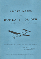 |
British Airborne Jeeps by Rob & Monica van Meel 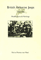 |
Thanks to
 for
the review kit.
 Please to help the reviews continue, thank you

