
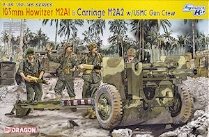
105mm Howitzer M2A1 & Carriage M2A2
w/USMC Gun Crew
DML 1:35 Scale Smart Kit No. 6531
Kit review by Terry Ashley

The standard of moulding is very good overall with clean crisp detail with just the usual mould seam lines and moulding plugs to be cleaned especially on the numerous smaller parts in the kit. There is also the odd pin mark about the place but the major parts such as the shields are blemish free.
The kit can be built in sub-assemblies with these bought together for final assembly which allows you to work on one sub-assembly while the glue another dries with some of these sub-assemblies designed to be positioned such as the trails or movable allowing gun elevation or traverse but these depend on the assembly as well will see.
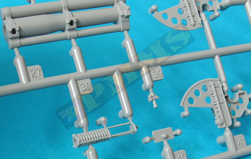
If you wish the gun to elevate then you shouldn’t glue the central equilibrator rod (part A9) to the spring equilibrator (part A38) or the spring equilibrator to the small attachment bracket (part A32) on the bottom carriage, this will allow some movement but as mentioned not accurately other than the 25 ° elevation.
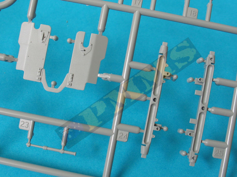
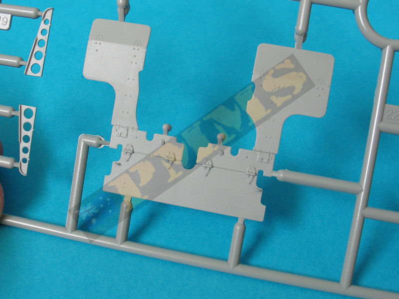
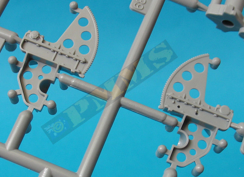
The two halves of the top carriage (parts A28, A41) have the upper elevation arc and the lower carriage moulded together with the addition of the small shield mounting brackets. These brackets are actually too short by about 1.5mm meaning the angle of the small shield is incorrect if fitted as indicated but by adding a small plastic strip spacer to the ends of the brackets the shield should sit correctly when fitted later.
The one piece mouldings do make assembly quite simple but detail definition is compromised as a result such as the bolt heads on the arc mountings that blend into the arc itself lacking definition as does the traverse cylinder assembly on the left side.
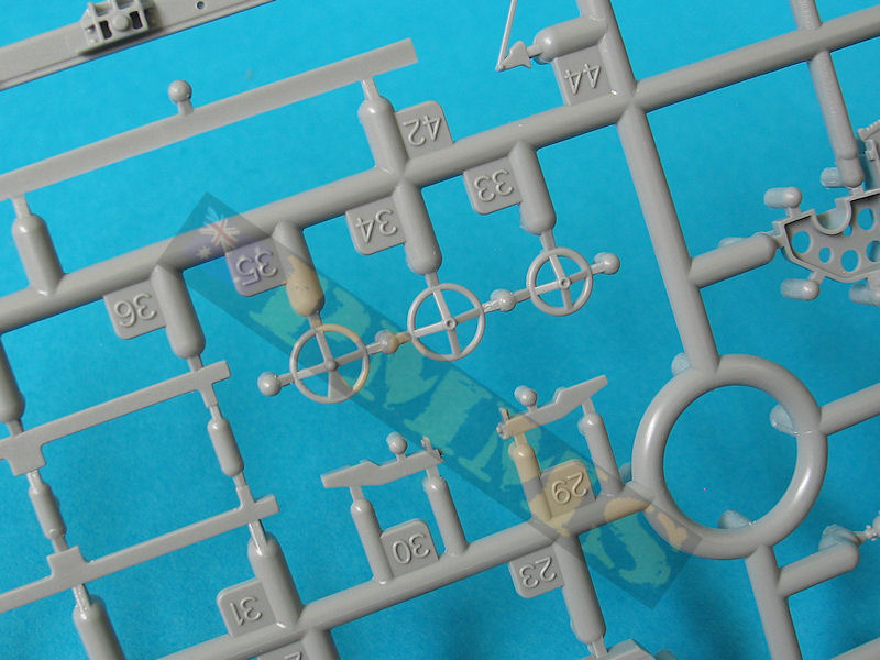
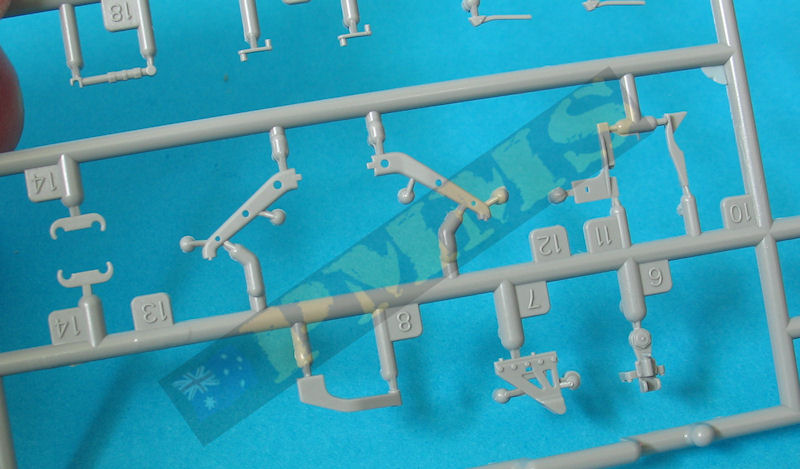
The instructions show to attach the elevation arc/carriage parts along with the delicate elevation hand wheels and connections to the gun carriage halves (parts A13, A43) before joining the carriage halves together but this is really not a good idea and leaves parts open for damage as well there is the central join seam on the carriage to deal with. It is best to assembly the gun carriage first before adding the top carriage and other smaller details.
There are two triangular strips that fit inside the cradle and you should ensure the correct orientation for these as indicated in the instructions with the remaining detail added without any problems. These strips should have a small lip on the rear edge but this is missing with just flat ends and adding this lip will enhance the detail.
Detail around the rear of the carriage is also quite simplified with a lack of rivet detail as well as the travel lock pegs being just plain without any detail, these pegs on the actual gun are not equal lengths but the kit pegs are and the right hand peg should be shortened to replicate this feature.
With the carriage assembled this can then have the two halves of the top carriage attached, if you want the gun to elevate make sure you don’t glue the gun trunnions and added to the side of the carriage is the traverse wheels and linkages which fit without any problems.
The main issues are:
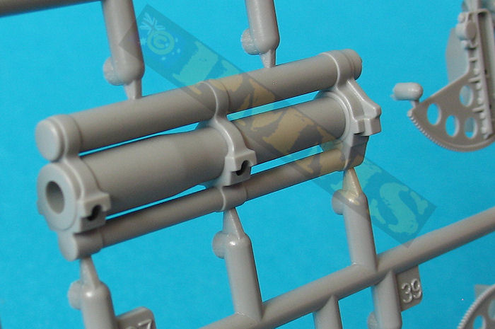
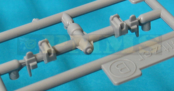
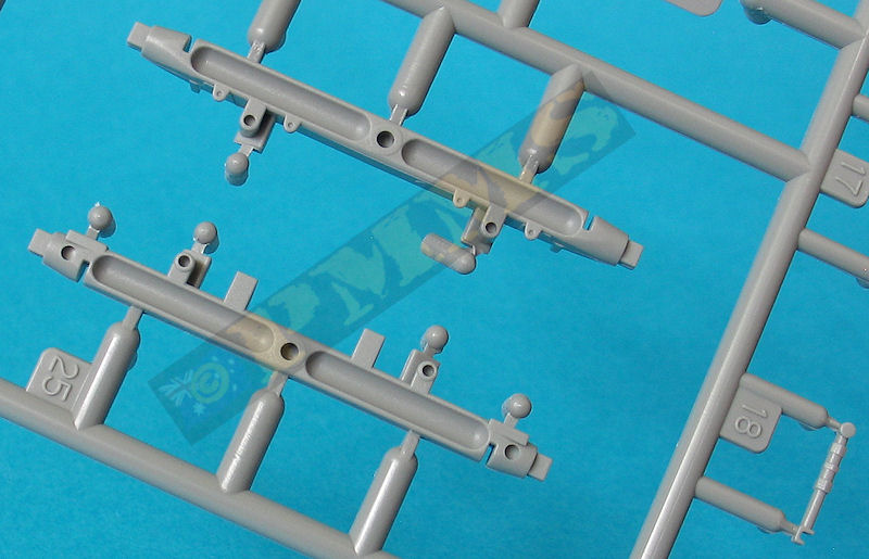
- The detail on the recuperator cylinder front head is simplified
- The length of the head is too long and the raised notches around the front of the recuperator cylinder are missing.
- The reinforcing ridges are missing from the central and rear sleigh supports.
- The lower recoil cylinder is missing altogether. Note the recoil cylinder is hidden inside the cradle in firing mode, so if not showing the gun in recoil isn't really an issue.
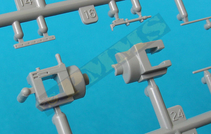
The breech ring is split vertically in the conventional manner that again results in the join seam needing to be eliminated which is a little tricky around the rear contours. The most notable feature of the breech is the breech block actuating lever is moulded closed with the breech, this means you can’t accurately show the breech block open as the lever would then need to swing out accordingly. The lever sits into an indentation on the side of the breech and would need quite a bit of work if you wanted to accurately show the lever open along with the breech block.
Detail on the breech block is a little basic in any case and would need some work if shown open so maybe easier to leave in the closed position?
As mentioned the whole barrel/recoil assembly is designed to just glue into the gun cradle but you may want to leave this separate to aid in painting as it can be added at any time.
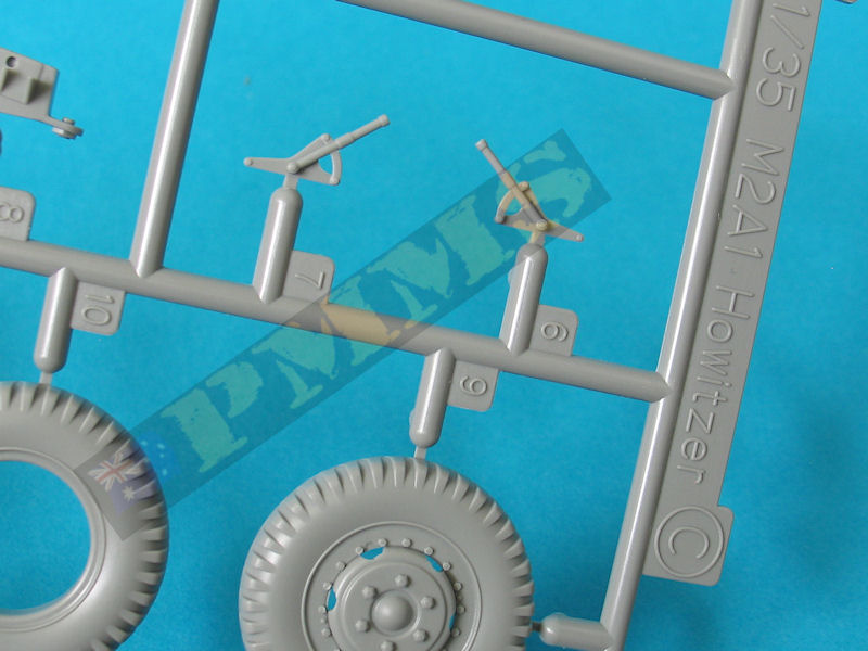
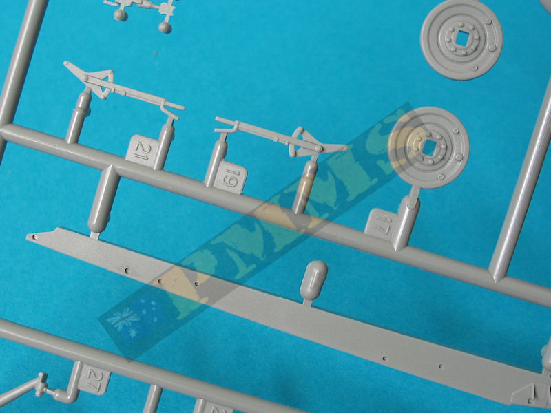
The left side Telescope Mount M21 and right side Range Quadrant M4 are made up of multiple parts for good detail definition but some of the detail is a little undersized such as the eye pieces and control knobs but otherwise serve their purpose adequately.
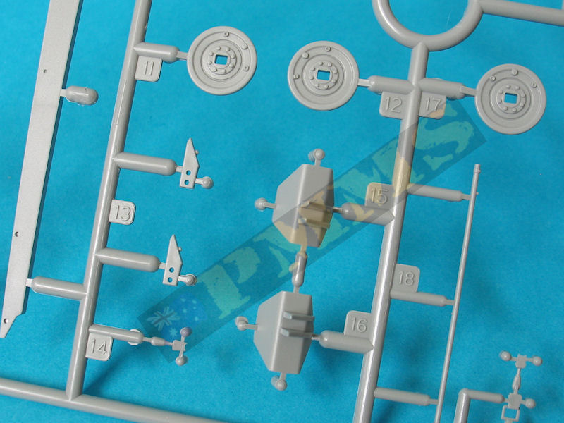
The wheels in the kit are the later combat rim with non-directional tread combat tyres without any sidewall embossing and not the more common “Firestone” combat tyre seen on WWII guns but being in two halves each again make for straightforward assembly and the wheels are all plastic which some may prefer.
On the carriage the two small axle lock levers (parts B17) shouldn’t be fitted until after the larger shields later in the assembly.
The top carriage is attached to the bottom carriage by way of a large central post on the equalizing support bar with the instructions showing not to glue this to allow gun traverse but there isn’t anything to actually hold the parts together and gluing these will prevent the assemblies coming apart at any time.
The locking arm brackets (parts c13) are moulded solid meaning you have to cut off the bracket tabs on the axle to fit the trails in the firing position, the trails themselves are not designed to move and have to be glued into the required travel or firing position so you need to make this decision as the trails are attached to the axle mountings.
The two part draw bar can be fitted in the towing or firing position as required so you should decide this and glue the bar in the appropriate position along with the position of the trails. Much of the detail on the trails is again lacking detail definition such as the rear locking clips which are moulded solid in one piece for travel or two pieces for firing mode,
The rivet and bolt head detail on the shield is a little under done in places while the large inner mounting brackets have oversized lightening holes but the kinked sections of the brackets have the correct profile.
The smaller outer shield is again moulded in one uniformly thin part free of any pin marks or other blemished with separate mounting bracket arms and a one part sight storage box with the mounting brackets moulded onto the shields.
The left side mounting bracket arm has the incorrect profile (shape) but the lightening holes are the right size. Fitting the outer shields is a little tricky as there is not a lot of room to get at these with the larger shields and other items on the carriage in place so care is needed while fitting.
As noted above the lower shield mounting brackets (parts B10, B11) are too short resulting in the small shield sitting at the wrong angle with the bottom edge leaning inwards and you should add a small 1.5mm spacer to the end of the brackets from thin plastic strip to allow the shield to sit at the correct upright angle.
The six options are:
- USMC, Iwo Jima 1945
- US Army, Iwo Jima 1945
- US Army, Iwo Jima 1945
- US Army, Iwo Jima 1945
- 3rd Battalion USMC , Iwo Jima 1945
- US Army, Iwo Jima 1945
The standard of moulding is very good as is the overall fit of the parts and if accuracy and the finer details are of no concern with build ability the main criteria then this kit will do the job nicely and the addition of the gun crew will allow a nice diorama setting to be made.
Rating 7.5/10
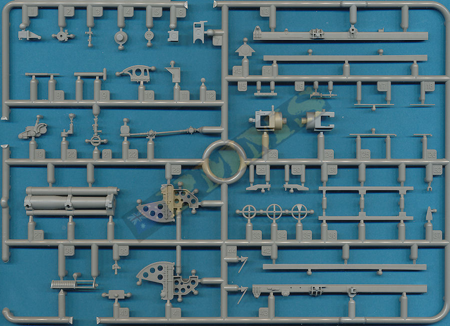
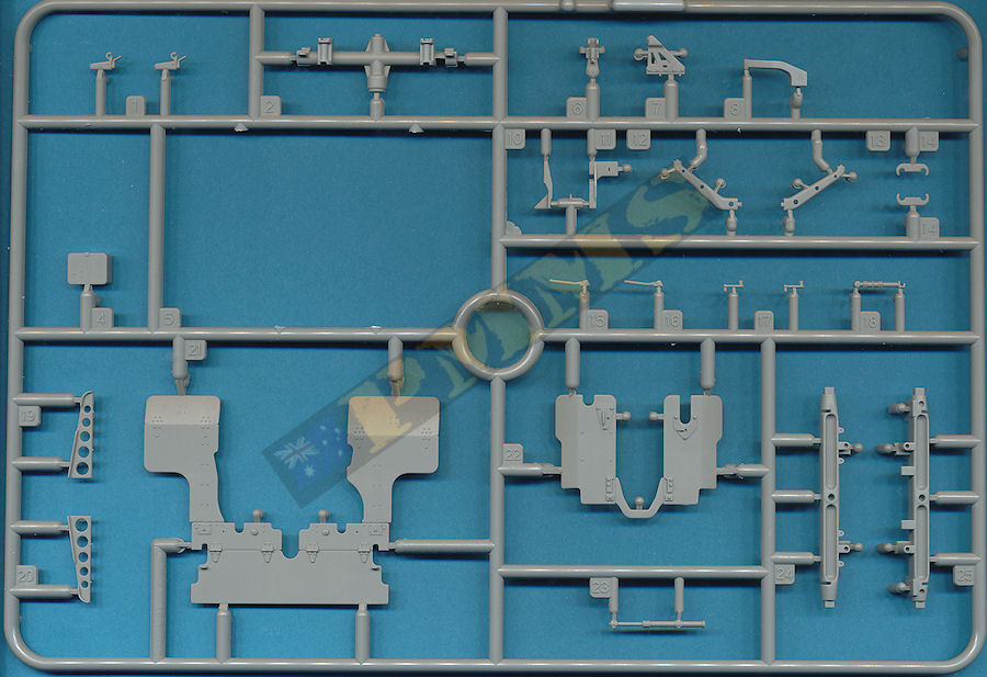
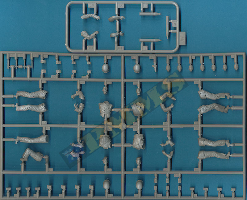
Sprue images
Click on thumbnails for larger view

Build images
Sprue detail images


| M101A1 105mm Howitzer in detail Wings & Wheels Publications R 048  |
U.S. WWII 105mm Howitzers M2A1 & M3 Tankograd Technical Manual Series No.6016  |
TM9-325 105mm Howitzers M2A1 Carriages M2A1 and M2A2 Easy 1 Productions CD-ROM #T003  |
 and
and 