
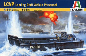
LCVP
Landing Craft Vehicle Personnel
Italeri Kit No. 6441
1:35th Scale
First Look Review by Terry Ashley
The Boat:
The LCVP often just called the “Higgins boat” was designed by Mr.
Andrew Higgins whom Eisenhower referred to as the man who won the war and was
designed to land a platoon of 36 men with their equipment, or a jeep and 12
men via the forward ramp, turn around without broaching in the surf and return
to its transport LST.
This ability allowed Commanders to plan operations without the need for capturing
ports with wharves facilities to land large quantities of men and equipment
and then re-supply the beachhead.
The LCVP was basically constructed of wood and proved to be tough and highly maneuverable with some 23,358 LCVPs being built between 1942 and 1945 and continued in service long after the end of the war in various roles.
It has been said that without Higgins' uniquely designed LCVP there could not have been the mass landings of troops and material on European or Pacific beaches, at least not without a considerably higher rate of Allied casualties.
Specifications:
Construction Material: Wood (oak, pine and mahogany)
Displacement: 18,000 lbs. (light)
Length: 36'3"
Beam: 10'10"
Draft: 3' aft, 2'2" forward
Speed: 9 knots
Armament: 2 x .30-cal MG
Complement: 3
Capacity: 36 troops or 6,000 lb. vehicle or 8,100 lb. general cargo
Power Plant: 225 hp. Diesel (gray) or 250 hp. gasoline (Hall-Scott) engines
The kit:
The kit consists of 157 parts in light grey plastic, a length of 0.8 rope and
0.3 twine plus the decal and instruction sheets.

The main hull is in a single tub with separate front ramp and the details on the hull bottom are well defined with weld seams around the forward plate and separate keel and rear screw/rudder assembly. The details on the hull sides are a little compromised due to moulding constrains that see some rivet heads deformed but may not be that noticeable on the finished model and of course these can be replaced if desired, although there are quite a lot.
A four part stand is also provided to display the model if not incorporated into a sea diorama scene and includes a decal name plate.
On the inside of the hull there is quite a bit of detail and an ingenious way of portraying the exposed ‘rib’ side panels. The inner well deck walls have the top and bottom panels with an open centre section with all the ribs (20 per side) added separately from behind so when the well walls are added to the hull the ribs are shown exposed. Each rib is individually numbered in the instructions so make sure you glue each in the correct sequence to allow for the hull contours.
On the starboard side is the ramp raising/lowering winch and guide assembly with the sliding pulley assembly able to fit forward for a lowered ramp and back for a raised ramp so make sure this is correctly positioned depending on your ramp position.
The cabling for the ramp is provided and this needs to be threaded though the various pulleys and deck holes as you assembly both the ramp mechanisms and the hull sections. The cable goes from the winch to the starboard and port upper pulleys with the cabling going under the well deck floor as per the real thing and you must thread the cable under the floor and up the other side again as you assembly the parts.
This may be a bit tricky but you can just position the thread and then tighten after the well deck floor and hull sides have been assembled so shouldn’t be too much of a problem and will result in a correctly cabled ramp.
The ramp itself has the forward bow section as a separate part as is the upper hinged vision hatch with the lower hinges designed with the outer hinge clipping into a small notch on the lower hull side allowing the ramp to be raised or lowered but watch the cables if the ramp position is moved.
The well deck floor has nice details on the central panels and non slip plate sections down each side with the contours to fit the deck sides included.
The lower rear deck is also a separate part with offset locating lugs to make sure it is attached the right way around and includes the raised engine compartment and exposed coxswain's station which has a separate throttle lever and wheel plus small decals for the instruments. Forward of this is a separate bulkhead that forms the rear of the well deck and front of the engine/wheel house deck.
The upper deck section has the rear deck and long side extensions that have additional smaller fittings attached including the two rear machine gun turrets with separate upper and lower sections plus gunner seat and are able to rotate to any position as required. The large splash guard plate is also a separate part on the top of the rear deck.
The fit of all the major hull and deck components is excellent with test fitting not showing up any areas of concern.
As mentioned there are numerous small fittings added around the hull including the side hull reinforcing brackets and all mooring attachments with rope “bumpers” that have quite good detail included as do the two buoys on the inside of the well deck. The side bilge pump openings have separate lips as well as separate sea hooks located on the inside well deck walls.
The two .30cal machine guns are a quite chunky in appearance but have separate ammo boxes and the gun shields are completely free of pin marks with the sides bevelled for a thinner appearance.
Also included are three crew figures wearing quite bulky wet weather gear with the two gunners being identical which doesn’t make for much variety but if the turrets are posed at different angles this may not be that noticeable. The standing coxswain has arms posed to hold the wheel and has slightly different body details from the gunners with each figure having separate steel helmets.
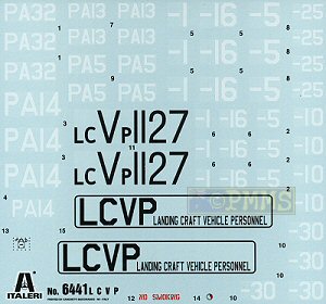
Decals:
The large decal sheet is well printed with good colour register and reasonably
thin carrier film with a good selection of boat numbers for the hull sides
and lower well deck floor.
The instructions show markings four 4 boats;
Each boat has five view plans showing the paint schemes which is basic medium grey for the US Navy boats and a nice grey/white/black/pale green scheme for the RN boat but just a quick note on the overhead plan which shows the coxswain's station on the starboard side but this should of course should be on the port side.
Alternate markings are provided for the US Navy Iwo Jima and Normandy schemes which allow some variation if you wanted to incorporate a couple of boats in a diorama?
Conclusion:
Overall this is a nice representation of this important boat with the main
features captured well including the ramp and cable mechanisms nicely done
and while there are a couple of areas needing attention the kit will build
into a good model of the LCVP with room for additional details to be added
as desired.
This kit will make an excellent companion to the larger LCM (3) for some very interesting diorama potential.
Highly recommended
Click on thumbnails for larger view


Close new window to return to review
References:
The Higgins Boat Project
LCVP - Landing Craft, Vehicle, Personnel
Thanks to Italeri for the review kit.
Page created 14 July 2005