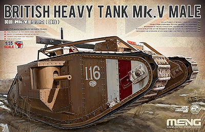
British Heavy Tank Mk.V Male
Meng Model 1:35 Scale Kit #TS-020
Review by Terry Ashley
Part 2 the Kit Build
Page 1 of 4
I will follow the instructions steps to show the assembly and any alterations/issues plus of course with the interior you would naturally paint the parts as you proceed with the assembly.
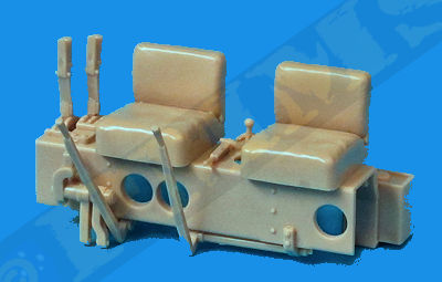
Before starting the assembly proper there are three poly caps used to attach the two 6pdr guns and the hull top telescopic pole and it is best to secure these poly caps in position under the top hull and the two gun mountings first so the glue has fully dried when it comes to the full assembly later, these poly caps are added in steps 47, 52 and 56.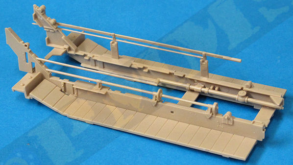
Note the top temporary sprue for easy fitting which is then removed when the glue has dried.
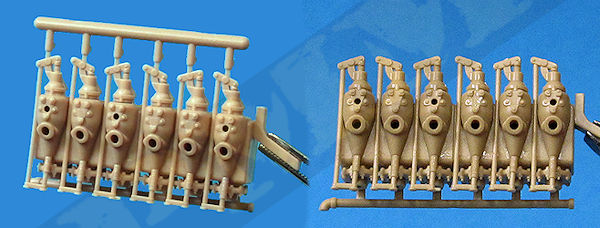
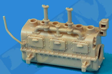
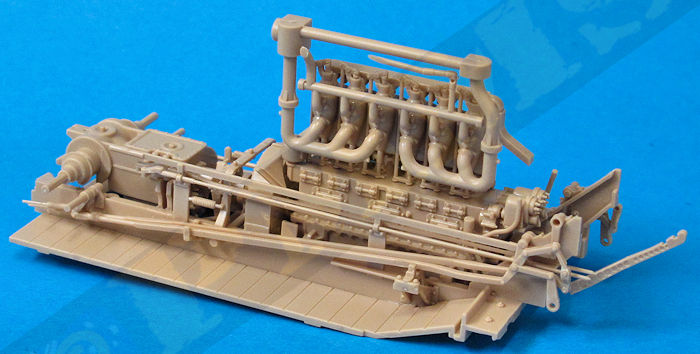
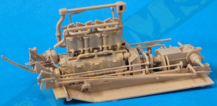
The other manifolds all fitted easily, just make sure these are aligned correctly as you glue in place and leave this for the glue to dry before fitting to the lower crankcase, also watch the orientation of the lower bearings (E19) the locating pins are different sizes on each side but still make sure not to fit the smaller pins in the larger holes or you won’t get the larger pins in the smaller holes later.
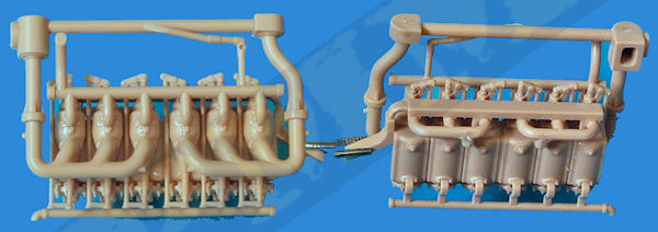
The lower crankcase is in three main parts fits together easily with the large manifold added, the smaller pipe (E33) sort of just hangs out there at this stage and should be fitted vertical to the crankcase.
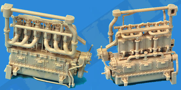
The rear sections and some fine piping added to the engine, these all fit without problems just take care removing the mould lines from the piping as they are quite thin, these also attach to the underside of the crankcase for a positive fit.
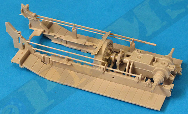
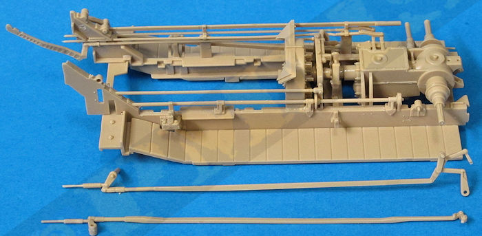
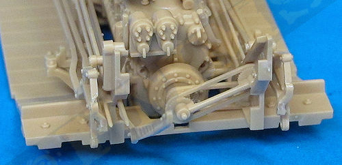
The outer pairs of link rods are firstly glued together and then attached to the outside of the engine rack and also resting in the supports added earlier.
While a little fiddley to get the inner rod aligned, they all fit precisely once aligned correctly.
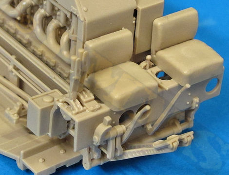
Right side linkages attached, lower image shows how (G10, G19) sit inside the frame.
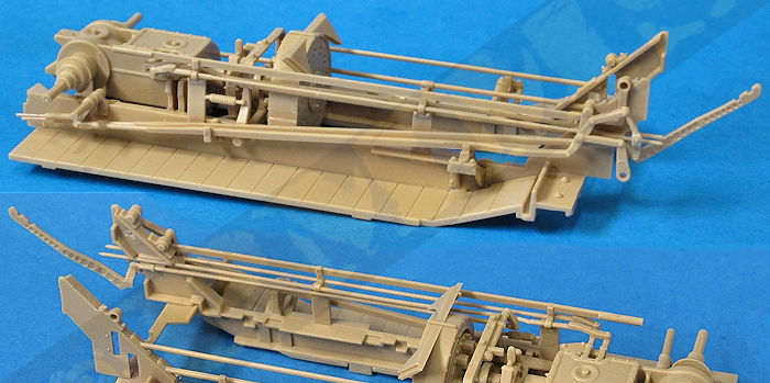
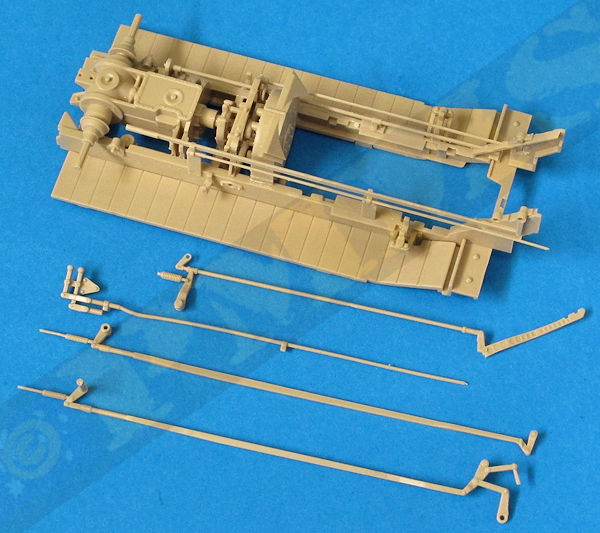
Left side linkages before fitting.
Left side linkages attached.
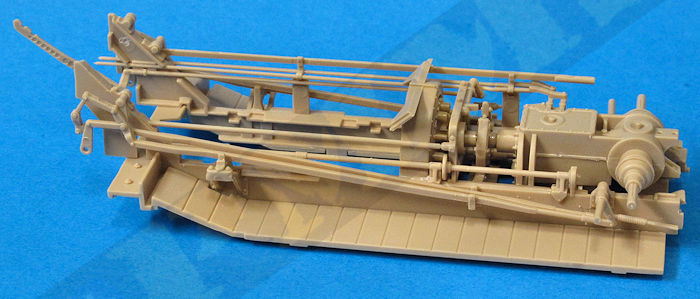
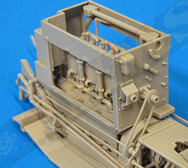
Additional images with the linkages and the engine fitted.

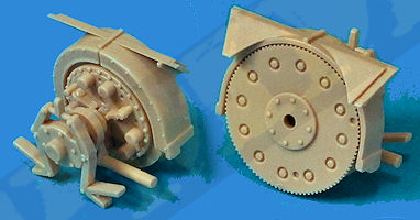
Front mounted pulleys.
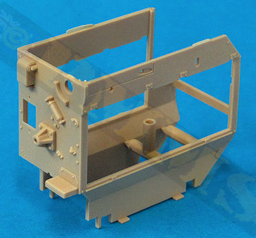
The fit of the lower rear section of the compartment where it meets the fairing moulded with the clutch was not very good, this being about the only part of the whole kit that didn’t match up perfectly and in hindsight it might be easier to cut these fairings from the clutch (E14) and then glue them in place to the engine compartment, any small gap between the compartment and the clutch will be incidental.
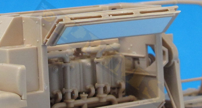
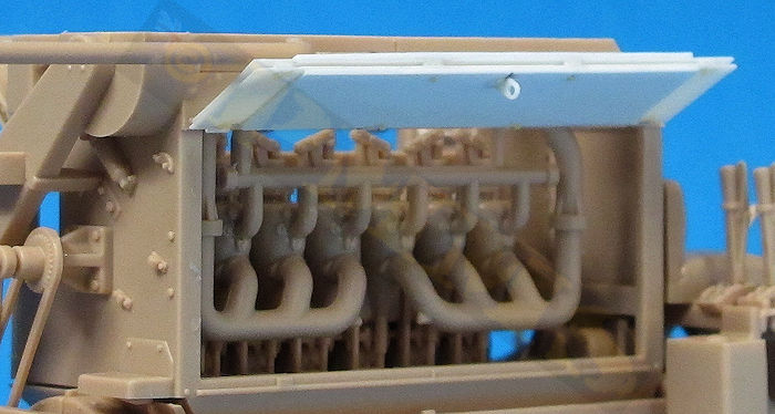
Meng give you separate side access doors for the compartment moulded as one flat panel either side but in fact these doors fold in half and then upwards to gain access to the engine and some modification of the doors will be needed to display them open. There is raised outline detail on the inside of the doors but this should actually represent an asbestos insulation panel on the inside of the door (correct me if I got that wrong, that is what is appears to be?) to represent this you should fill in the raised edges with plastic card. You then cut the doors in two lengthways along the hinge line and glue in the open position. The kit doors are a little on the thick side and if you were intending to use these in the open position making new doors from thin plastic card would be a good option and when folded open you only see the plain insides of the doors in any case as the outsides are folded together hiding the outer door details. (see images).
the doors are overly thick and have no details as they are not designed to be shown open, only fixed in the closed position.
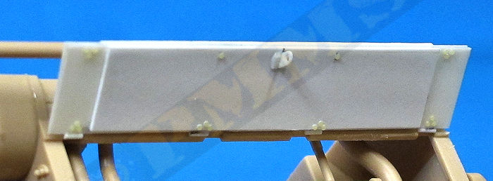
These are the doors made from thin plastic card with the appropriate inside details added
and when shown open they have a much better appearance.
To make these, I used the kit doors to size cutting the plastic card and added the inside raised section
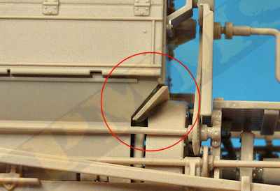
from slightly thicker card. The top securing bracket used to fix the door to a roof hook is also from thin plastic card.
The small hinge rivets (20 in all ) were added using small resin rivet heads made by Calibre35.
Close up of the exposed door showing the details as mentioned,
this will greatly improve the appearance if you wish to show the doors in the open position.
Reference image showing the open engine compartment doors.

Image provided by David Green
With the engine compartment in place the front guard (G26) and second driver’s foot pedal arm can be attached along with the rear compartment pulley that fits to the end of the top rod on the engine rack as mentioned in step 7.
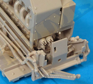
The two foot pedals are attached to the end of the support arms and just note the correct position for these as one has a large B and the other a large C embossed on the pedal.