
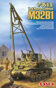
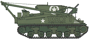
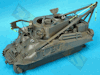
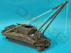
Tank Recovery Vehicle M32B1
Tasca 1:35 Scale Kit No. 35-026
Review by Terry Ashley
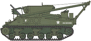
The hull retained the forward cal.30 MG for self-defence as well as mounting an 81mm mortar on the glacis although this was mainly used to lay down smoke rather than offensive/defensive use. In all 1055 M32 B1s were produced and came into service in NW Europe and Italy after D-Day with many continuing in service after then end of WWII with armies such as the IDF and others.
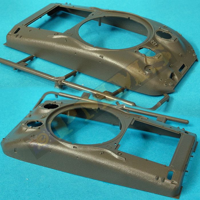
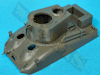
The kit uses many sprues from Tasca’s previous M4A1 kits along with new sprues with the dedicated M32 parts hence the many parts not used plus a newly tooled upper hull with separate fixed superstructure and also includes interior winch and storage boxes for the central fighting compartment but there is no forward driver’s compartment or transmission included.
The kit consists of:
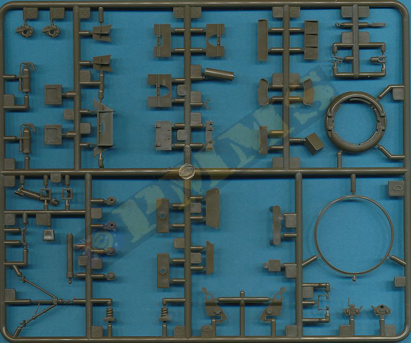
- 719 parts in olive drab plastic (with about 100 marked as not used)
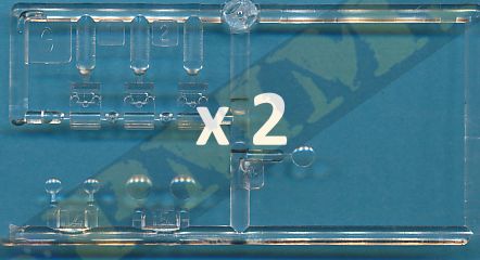
- 16 parts in clear plastic
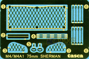
- 26 etched metal parts
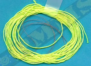
- 1 long length of twine
- 1 short length of thin twine
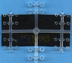
- 26 vinyl washers
- 1 thin rubber sheet 49mmx39mm
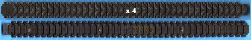
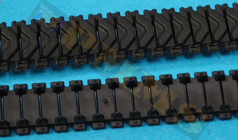
- 1 set of vinyl type T48 tracks in 4 segments
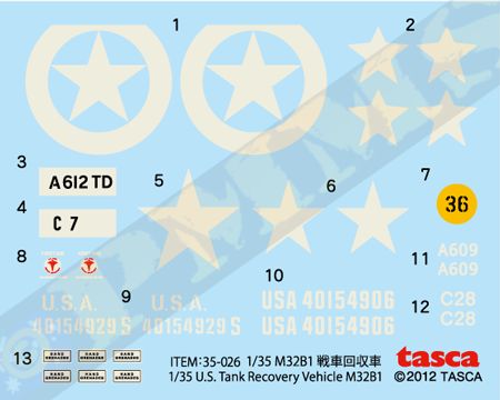
- 1 decal sheet
- 1 fold out instruction sheet
The standard of moulding is very good as with the previous Tasca kits with clean crisp details on the parts with just the odd bit of fine flash about the place. Some of the new parts due to their smaller side and nature do have some pin marks that need to be eliminated, some will require filling as they are fairly deep and in places that can be seen after assembly. Another thing to watch is that the plastic is quite hard and the smaller parts a little on the brittle side as a consequence and care is need when removing the small parts from the sprues. A few of these that had multiple attachment points were very difficult to separate without the part snapping requiring repair before assembly, so take care.
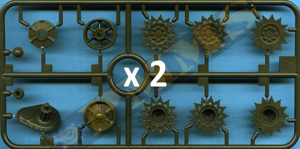
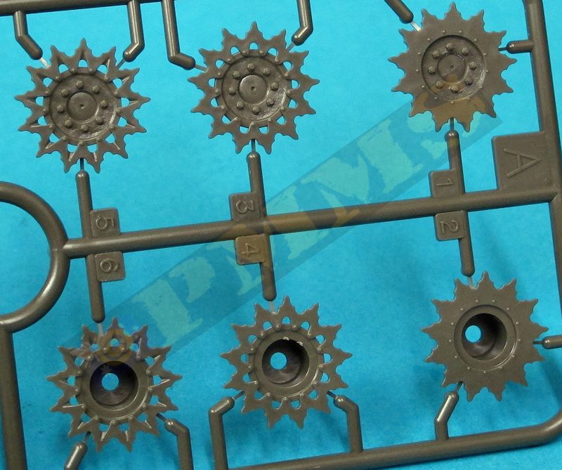
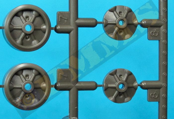
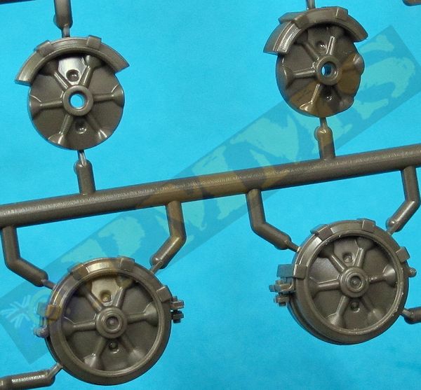
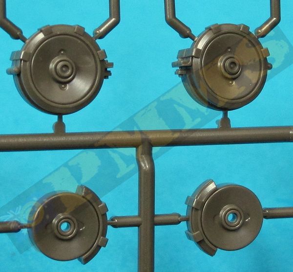
Included are open spoke or solid spoke wheels and a choice of three styles of drive sprockets with period images indicating the M32B1 mostly used the solid spoke road wheels with solid drive sprockets along with a set of vinyl T48 rubber chevron tracks in two segments per track run. Some period images show a mixture of road wheel types with one of the decal options having a mix of solid and open spoke road wheels.
It’s probably best to say up front this kit is not for the inexperienced modeller as there are many small parts and well as intricate sub-assemblies that have movable parts as well as the quite delicate A frame assemblies so it’s not a kit to rush into. Also there are numerous small sub-assemblies that need to be assembled and the glue fully dry prior to the main assembly and identifying these in the instructions and assembling first will make things easier further into the construction.
You also need to decide the final boom/winch configuration as there is a choice of three positions but it’s difficult to change the boom position after assembly due to the cable routing. The three positions are the lowered boom in the tank recovery/towing position, the raised boom in the lifting crane position and with the boom lowered and the winch cable routed out through the front hull hatch and large guide roller. As mentioned the A frame boom will easily pivot from the raised to the lowered position the issue is with the re-routing of the winch cable and the support cables used in the different configurations that requires you make a choice before assembly.
The kit includes quite a few parts from previous kits Tasca M4A1 kits with a number of turret and gun parts and the bolted transmission cover obviously not used with this kit as well as some duplicate parts with newer parts included for the B1 so you must take care to use the correct part as per the instructions.
The fit of the hull parts is superb with the engine bulkhead ensuring everything lines up correctly. There were no gaps or panel movement anywhere and the assembled hull tub is perfectly square so forget any trimming or filling. The internal winch parts also fit very well as do the sponson mounted storage lockers, just watch the alignment of these as indicated in the instructions.
The sponson covers also include the small circular access cover on the rear undersides which is common to all Sherman based vehicles and the hull side panels include the mounting plates for the suspension bogies.
The real hull panel is extensively detailed with separate engine access hatches, very detailed idler mountings in two parts plus the idler axles and the choice of round or square air cleaners made up of three main parts each with the attachment clips as etched and fine plastic parts as well as the lower towing shackles. You need to drill out two locating holes in the access doors for the angled intake grill, you should also note the small door handle should be fitted lower than indicated as it will prevent the grill from fitting as indicated, best to fit the grill and then the handle.
Also added to the rear plate is the large tow hook mounting box made up of six parts that fit together without any problems and also fits perfectly to the lower rear hull plate.
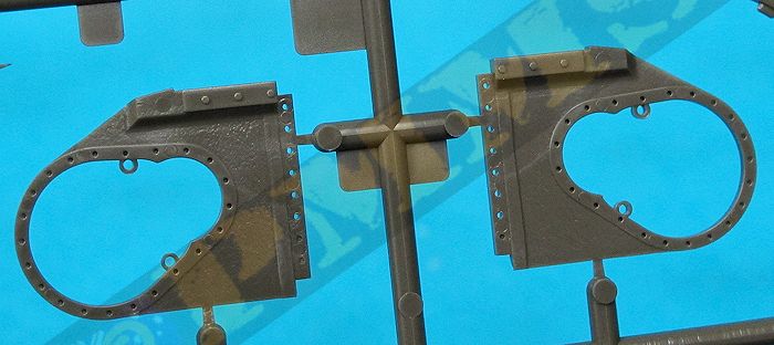
The single piece cast transmission housing has subtle cast texturing with the top and bottom bolted strips as separate parts for good definition. The side final drive panels are also separate parts hollowed out with bolt holes around the opening and hull mounting strip and there is again subtle surface cast texture included, the side panels have bevelled edges for a very good fit to the transmission cover and so long as you are careful everything fits perfectly.
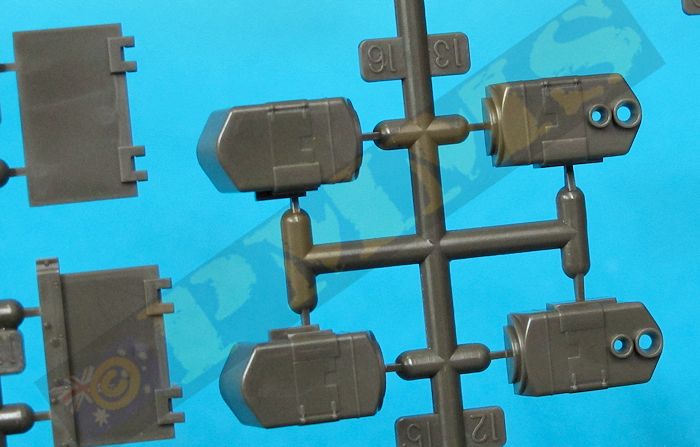
The outer final drive covers feature the correctly detailed axle hubs with the fit being very good to the final drive housings. There is again one small detail omission in that the two oil drain plugs are missing from the underside of the housing but these are easy to add from small plastic discs. The fit of the assembled front transmission to the hull tub is again superb without any trimming or filler needed with a second lower strip added to the hull tub that acts as a locating tab for the housing ensuring perfect alignment.
There is the front mounted tow hook mounting box made up of six parts but there are no locating marks on the transmission housing for the box, only plan diagrams in the instructions showing the location, so you need to take care to get the correct placement. The small draw bar is also added to the housing but again there are no locating points so make sure you don’t fit this too far up the housing or it will foul on the front winch guide when added later. Also note when assembling the draw bar the small brackets (parts M38) have small locating pins but no corresponding holes, so just trim off the small pins for a better fit.
Other than the central winch mounting and storage boxes there is no other interior provided but as you can just see into the forward driver’s compartment through the top crew hatches if open and through the large turret opening some may wish to add the front transmission and crew seats. There are numerous transmission assemblies available in various Sherman based kits from AFV Club, Academy and DML as well as aftermarket resin sets such as those from CMK. Whichever you choose some trimming may be needed to fit the inner Tasca hull contours but will fill the void if you wish.
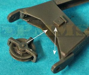
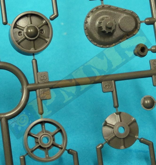
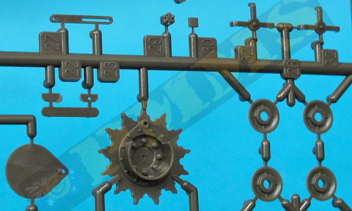
There are three types of drive sprockets included with two styles of fancy sprockets and the later solid plate sprocket with two types of idlers wheels, the open spoke and solid spoke which also have rear inserts. The kit includes a new outer right side sprocket with the lifting drum included; this has a separate outer plate and very small locking pin to secure the cable when fitted. The drum is moulded on the solid sprocket so obviously you use the remaining solid sprocket parts in the kit with the drive sprockets attached by the poly caps trapped between the sprockets halves.
The detail on the road wheels, idlers and drive sprockets is excellent with fine crisp details that include the grease plug and relief valve on all the road wheels and idlers with fine bolt head details on the inside of the drive sprockets. The actual solid spoke wheels feature twelve small rivets around the insides of the rims and these are provided moulded onto the sprues B which you have to cut off and position around the wheel rims yourself. This is quite a delicate job that will need a very sharp blade to carefully slice off the rivets and then patience and care to position each with a small dab of liquid cement around the rims.
Only enough rivets are provided for the outside wheels of each bogie unit but it would be difficult to see them on the inside wheels anyway and given the amount of work to add them this will probably save you from going completely blind after doing the outside wheels.
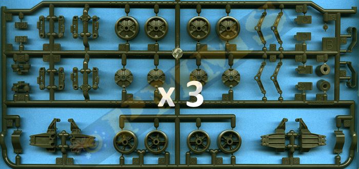
The bogie units don’t have any noticeable cast texture but there are fine casting numbers included which can vary in position depending on manufacturer and period and they also include the three bolts on the bottom of both bogie units.
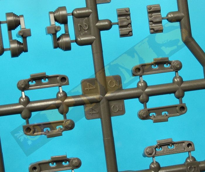
The bogies can articulate after assembly due to the separate lower suspension arms that trap the road wheels between them and are then in turn trapped between the inner and outer bogie halves. The upper suspension arm is in one piece as are the volute springs with three small sections of rubber sheet you cut from the larger sheet provided being added to the top of the volute springs that give the ‘spring’ when the suspension is depressed. There is alternate solid plastic spacers included to use instead of the rubber sheet which sees the suspension arms sit a little higher in the bogies giving a slight depressed suspension appearance so you may wish to check the correct ride height if using the plastic spacers?
The separate track skids allow you to fully eliminate the top join seam between the two bogie halves, but this is not very prominent and won’t take much to deal with but you will have the drill the four bolt holes on the front of the bogie units as with all other kit bogies. There is an important addition for the M32 bogies with the inclusion of the lock out brackets (parts N42, N43) added to the front of the first and last bogie units for when the vehicle is being used to crane lift heavy loads. These lock out brackets stop the suspension compressing due to the load and the brackets are stowed on the front glacis when not is use held in place by some very small bolts (parts N30) that do need extreme care in handling. Note the top bracket (part N43) is attached even if the lock out bracket is not fitted to the bogies, you may also wish to add the four bolt heads holding the lock out brackets in place on the front of the bogie as they just have the bolt holes in the parts.
In conjunction with the lock out brackets there are new suspension arms (parts N38, N39) that include the additional stops for the lock out brackets on the front of the arms and you should make sure to fit the new arms on the first and last bogies units with the standard arms on the central bogie unit.
There were no traps while assembling the bogies although the articulation is a bit redundant as you have to firmly glue the front and rear suspension in place to prevent the tracks distorting the road wheel sit which they will do if the suspension is left free. The fit of the bogies to the hull is as you would expect very precise without any movement of the bogies for easy assembly.
The contours of the cast hull are captured well from most angles and one thing to note on the cast M4A1 hull is the sides are not perfectly vertical (apart from the earliest models) but are angled in at slightly different degrees depending on the production foundry. Looking at the Tasca hull it appears to the eye they are vertical but in fact they are sloped inwards a couple of degrees to represent this feature nicely.
The first thing you should do is attach the various attachment brackets for the engineering equipment, most notably the side A frame mountings and those along the sides for the draw bar and spare drive sprocket storage and the small U cable brackets to ensure the glue is fully dry on the these when you come to fit the gear later. Just a quick note on the large U shaped bracket (part M42) for the left side draw bar as this needs the bottom of the longer side bevelled to conform to the hull sides as there is no actual cut-out in the hull to take this part. The large hull A frame mountings have some substantial pin marks that will need to be filled before fitting.
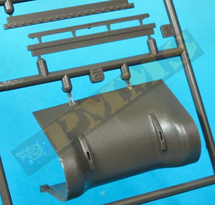
The engine deck is broken into two sections with the forward section having the covered intake and underside grills as etched screen to add should you wish to show this open. The rear panel is quite plain with just the moulded on grab handles and fitting the panels to the hull is trouble free as the fit is again perfect without the need for any trimming. The fuel filler caps on this panel are also separate with inner filler detail along with the separate hollow grouser covers with etched front mesh screens and looks very good when attached and the taillights feature the different configuration left and right so make sure you fit the lights on the correct side with the bush guards moulded quite thin but you may wish to replace these with etched guards to improve the appearance.
Moving to the front are the two nicely detailed small crew hatches that have separate parts for the periscopes which are in both normal green or clear plastic but there are a couple of inside pin marks to be removed plus separate periscope covers and there is also a very small hatch spring (in plastic) that requires care when fitting. On the inside of the hatch is a separate head pad that neatly covers the large pin mark present plus a small etched latch and the fit of the hatches to the hull will need the inside hatch sill trimmed a little to allow the hatch to sit in place snugly but if you position the hatches open this trimming isn’t required.
The hull cal.30 MG is provided with the full receiver and handgrip on a ball mounting that attaches to the outer shield allowing the MG to move after assembly. The barrel cooling jacket for plastic has nicely rendered cooling holes and the muzzle has a small indentation but you may want to drill this out further for a better look or even replace with any of the available metal barrels to improve the appearance further.
Two style of front fenders are provided that have very thin edges and raised strengthening ridges and either can be used while added to the hull front are the head lights with clear plastic ‘glass’ and plastic bush guards which were quite distorted on my kit and needed to be bent back to shape but again you may wish to replace these with etched guards to improve the appearance. Adding the front lifting hooks basically completes the standard hull fitting before moving to the many engineering additions.
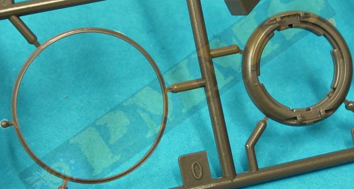
At the front is the large cable guide and cable hatch, the guide is made up of 11 parts that goes together well if a little fiddly, it is attached to the glacis by the small brackets (parts O37, O38) allowing the guide to pivot with the cable direction. It is very tricky to fit these small brackets allowing movement and it may be easier to simply glue them in place while the hull hatch can be positioned pen or closed if required.
Mounted on the glacis is the M1 81mm mortar with a separate bipod and two part mortar tube which is hollowed out at the muzzle, this assembles easily with the bipod legs fitting into brackets mounted in the gun travel lock brackets although there are no attachment pins and adding these will improve the detail. Fitting the mortar tube base into any of the three sockets is easily enough for a fairly simple assembly.
On each hull side are the spare drive sprocket racks with two small hull brackets and the two securing racks, the front securing ring is extremely small and needs care in fitting. The lower rack doesn’t have any locating points and it’s best to attach the top rack and line up the lower rack with the sprockets in place to get the proper alignment. The sprockets themselves have some shallow pin marks on one side that need removing or simply face them to the hull in the racks. On the upper hull are four spare return roller racks that go together easily, just watch the positioning of the supports as they aren’t evenly spaced.
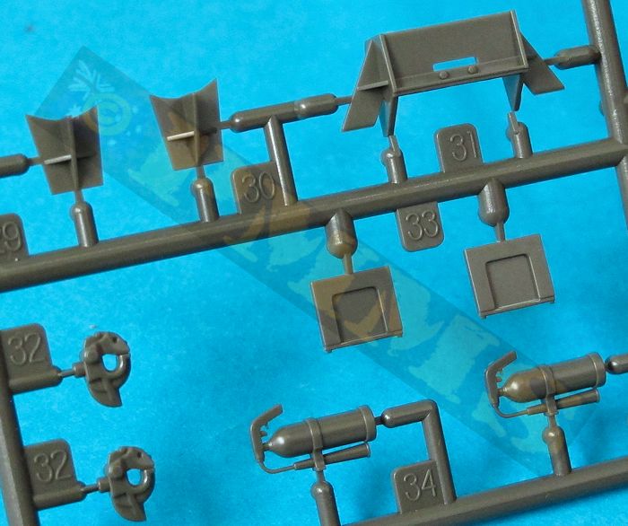
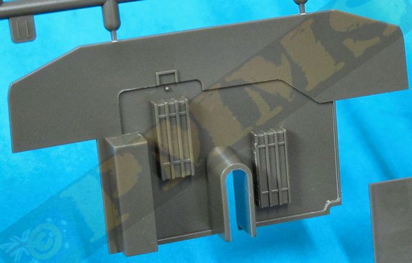
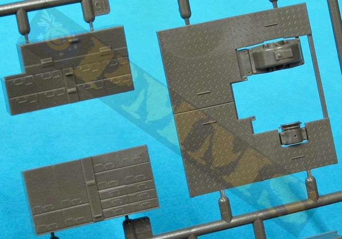
One the rear hull are the large A frame sockets (parts M15,M16,M17,M18) into which fit the bottom of the boom A frame support and these have recesses in the hull for precise location along with the large rear storage box and two smaller boxes mounted on the engine deck. The fit of the storage box parts was good but some of the joins on the smaller boxes may need attention to get a smooth finish. All the pioneer tools on the large box have moulded on tool clips and brackets and replacing these with etched items will again improve the appearance, take care as some of the tools have been revised for this kit and the older tools are still included so make sure you use the appropriate ones leaving the others as spares. Also added to the rear hull are two more spare road wheels and check the alignment of these with the instruction diagrams.
Stowed on the engine deck are the two large track chocks placed under the front track when in the crane lifting mode and these fit together easily but there was a fair amount of fine flash on the chock parts in my kit which is easily removed. The two large snatch blocks are also stowed on top of the chocks and when assembling the blocks make sure the top bracket (parts N11,N1) is movable to allow the snatch block to be used in any situation should you wish. It’s best to glue the two bracket halves together and then clip over the small pins on the block once dry for the best result.
There are four crew seats added under the hull top deck on posts provided and the instructions indicate to glue the seat back rests to the rim of the turret mounting ring but this is incorrect, you should only attach the rear two back rests to the ring and the front two on the inside of the front turret wall.
The fit of the four turret walls was good although I had a problem with the curved front plate as this had been damaged in transit and almost flattened meaning I had to bend it back to the right curve and this may have resulted in the bit of trimming needed to fit at the sides and subsequent sanding and filling of the join seams. In any case the join of the front plate to the side plates has to be completely eliminated as this is one continuous plate of the actual turret.
The separate roof has a separate fine lip added around the front gun ring and the gun pintle mounting bracket (parts O17,O18) glued around the lip to allow this to slide around the gun ring after assembly and this goes together without any problems. The fit of the roof to the turret walls was excellent without any gaps or trimming needed and the rear Commander’s hatch ring can be added along with the split hatches. These have a couple of shallow pin marks on the inside should you show them open along with separate clear or solid plastic periscopes and small grab handles.
Added to the front of the turret are the two spare road wheels and the spare track racks added to the rear wall with the fit of the turret mounting ring to the hull being a very precise and positive fit not needing any trimming. Also included is one of Tasca’s excellent M2 cal.50 HBMG which comes with the hollow support jacket and separate barrel tube for an excellent representation of the gun in plastic.
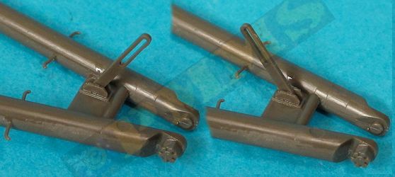
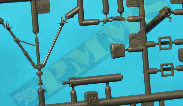
The main A frame is an impressive moulding with the correct scale diameter frame, the earlier A frame was slightly thinner but this correctly depicts the later frame, this also has the numerous small delicate foot-steps along the frame and yes these will break off if you dare look at them sideways. Thankfully Tasca include some spare steps should you lose some along the way but it may be an idea to replace the steps with thin wire inserted into drilled holes in the first place to avoid having to continually repair these as it’s almost impossible to handle the A frame without breaking some off.
The large lifting arm with the three attachment eyes has some pin marks on one side that have to be eliminated before fitting to the boom, thankfully these is a recess in the jib frame to seat the lifting arm securely and in the right position. Added from the lifting arm to the top of the A frame is a support wire from the thin thread provided and this has some extremely small plastic cable bolts that really do need care removing from the sprues and in handling. After assembling the cable making sure you have the exact 140mm overall length as indicated in the instructions you should firstly firmly glue the attachment bracket (part M37) to the top of the lifting arm (with the cable fitted) and leave overnight for the glue to dry thoroughly as this will take some stress when you attach the other end of the cable. You could of course replace the plastic bracket with thin wire inserted into a pre-drilled hole in to frame to make sure it won’t be going anywhere, but the plastic bracket has held okay on my kit so this is up to the individual.
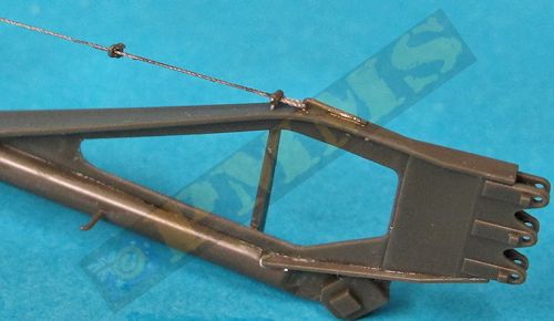
When fitting the end bracket you have to tension the cable slightly to ensure there is no sag and this is where getting the exact length of the cable correct when assembling the cable becomes important, the end bracket (part M31) has a large recess in the frame to ensure a secure location and you then leave this to dry completely.
There is a three part bracket added under the A frame (parts M22,M23, M27) and you must ensure the central arm is left free to move after assembly so this will align correctly when you fit the smaller support A frame so be sparing with the glue on this small bracket. The hole in the end of the arm (part M27) should be drilled with a 0.7mm drill to allow the pin on the small mounting bracket to fit properly.
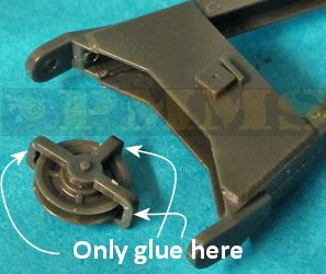
The smaller support A frame has a two part pulley trapped between the top end and this pulley has to be left movable after assembly to aid in threading the cable later and there is four support cross plates added to the arms to assemble the frame. Added between the large cross plates (parts M11, M13) is another two part pulley with cable support bracket and its best to assemble this so the pulley and bracket are free to move independently just like the real thing, this means only gluing the ends of the three bracket arms and I used small clamps to hold these securely together until the glue had dried but I didn’t fit this pulley assembly to the frame at this point, waiting till I had assembled the larger cables later.
The assembled support A frame clips securely into the top of the main A frame with the small bracket arm (part M27) fitting through the opening in the support A frame and secured with a small pin (part M51), just make sure you don’t glue the arm when fitting the pin so it is free to move as the position of the support A frame changes.
Added to the foot of the main A frame are the attachment brackets (parts M3,M4) and again make sure these brackets are securely glued together with the frame free to move and let the glue dry completely before fitting the frame to the hull mountings. The main A frame can then be glued to the hull mounting brackets and again left for the glue to dry completely before moving the A frame or fitting the cables.
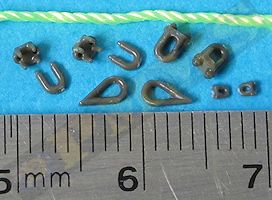
The cables are cut from the nylon thread provided and the smaller lifting arm cable has an overall length of 85mm for a final length of 50mm when you overlap the cable ends, there is a small teardrop eyelet at the end of the cable with the securing bolts used to hold the cables in place again just like the real thing and I used cyanoacrylate to glue the cables and bolts together for a secure join.
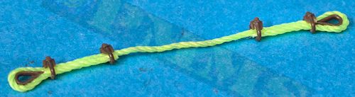
The crane cable can be any length really depending if you are using it on the lifting or towing frame position, I used a length of about 350mm and assembled the eyelet and securing bolts the same as above. The main crane support cables attached to the rear hull brackets are another story and require a bit of forethought.
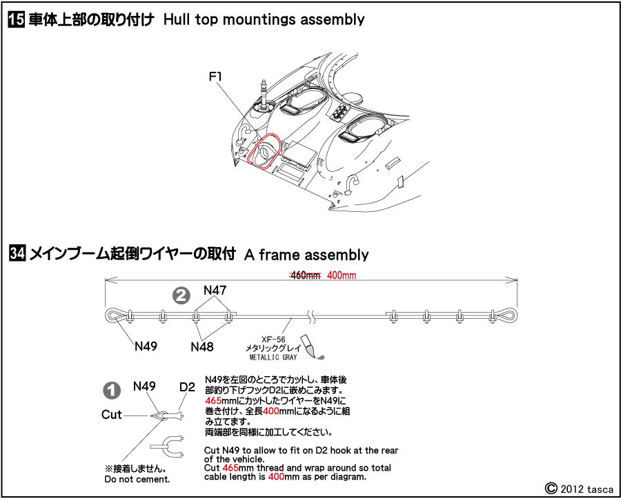
Firstly the instructions show the incorrect length of thread to cut for the support cable, it shows an overall length of 525mm with the final length of 460mm when you overlap the ends of the cable, but the final length should actually be 400mm not 460mm with an overlap of 32.5mm each end giving 465mm for the length of thread to cut not 525mm.
Update: Tasca have posted an instruction error correction on their site, see this HERE
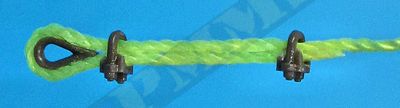
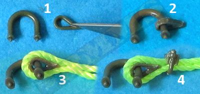
The cable is first threaded through the top pulley assembly done earlier and then you loosely slip the four U bolt brackets over each end of the cables ready to be used later, the eyelet then has to be fitted over the hull lifting bracket (parts D2) and you have to cut the eyelet apart to do this as indicated in the instructions (step 1 below). You need to ease the cut eyelet over the base of the hull bracket as it can snap apart if you expand it too much requiring repair which is a bit fiddley. Once in place re-glue the cut to secure the eyelet ensuring not to glue it to the lifting bracket. (step 2).
The cable thread is then glued around the eyelet using cyanoacrylate and again taking care not to glue the bracket (step 3). The pre-assembled U bolts can then be slid over the double cable and secured in place with a small dab of cyanoacrylate and the process repeated for the other hull bracket cable (step 4,5).
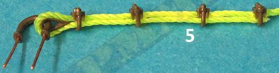
Note the wire pins in the hull bracket were added to allow me to remove the brackets when altering the A frame position for the review images, but they also allow the brackets to be attached without glue should you need to make any alterations to the cable length but are not required for normal assembly.
The top pulley assembly can then be fitted between the support A frame plates by slightly prising open the gap between the two cross plates using closed tweezers to widen the space between the cross plates just enough to slip the pulley assembly between them. This pulley assembly will clip into the locating holes when aligned properly and while it sounds daunting is actually easier than it sounds, I used the same method to remove the pulley again after I discovered the cables were too long going by the instructions so I have actually inserted and removed the pulley a few times during fitting using this method.
Depending on the chosen configuration of the A frame the cables can be treaded though and the end fed into the appropriate turret opening and glued to the drum using cyanoacrylate to finish off the assembly.
Option 1 is shown on page 36 of the Ampersand Heavy Wrecker book and shows a mix of open and solid spoke road wheels with T51 rubber block track fitted.
Option 2 is shown on page 36 of the Ampersand Heavy Wrecker book and shows all solid spoke road wheels with heavily worn T48 rubber chevron track fitted. This also shows additional brackets welded to the A frame boom which you may wish to add for a truly accurate model of this vehicle.
|
The standard of moulding and level of detail included is outstanding and will build into an impressive model of the M32B1 with very good part fit overall along with the option of displaying the A frame boom in either the folded or extended position. As mentioned with a little forethought it is possible to change the cables and A frame position after assembly but easier to choose the required position before hand and go with that.
The lack of driver’s compartment and transmission is not a big deal as it’s hard to see and very easy to remedy with any of the available transmission should you won’t to add this and as with any kit there is room to add even more detail to really make an outstanding model even better.
Rating 9.5/10
Click on thumbnails for larger view


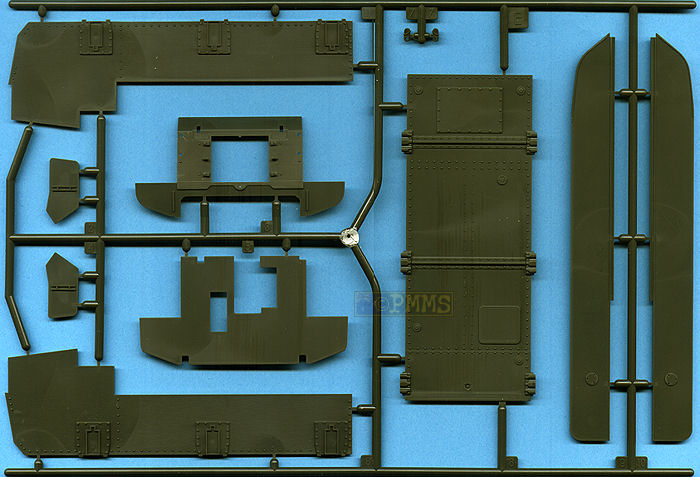
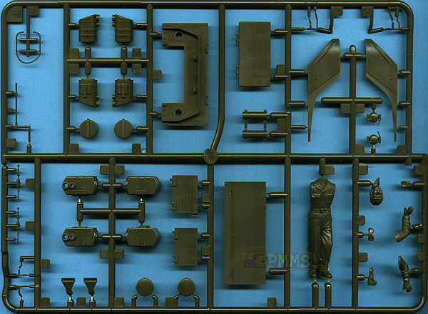
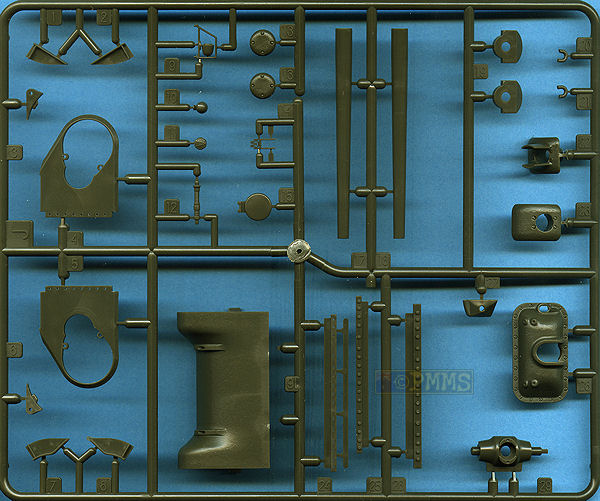
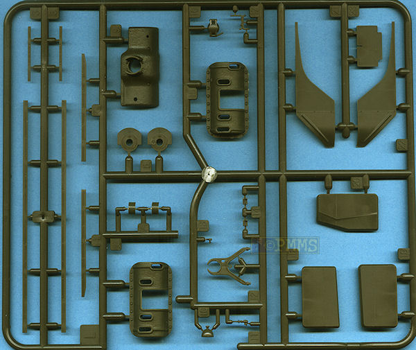
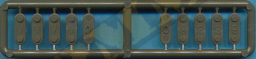
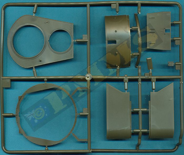
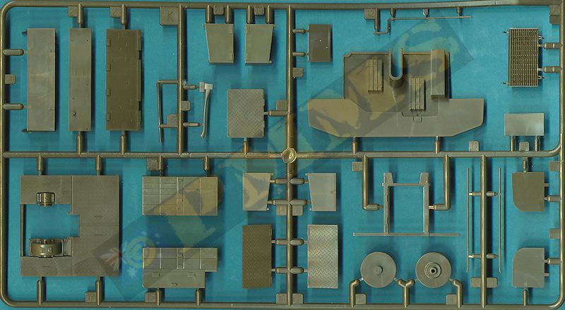


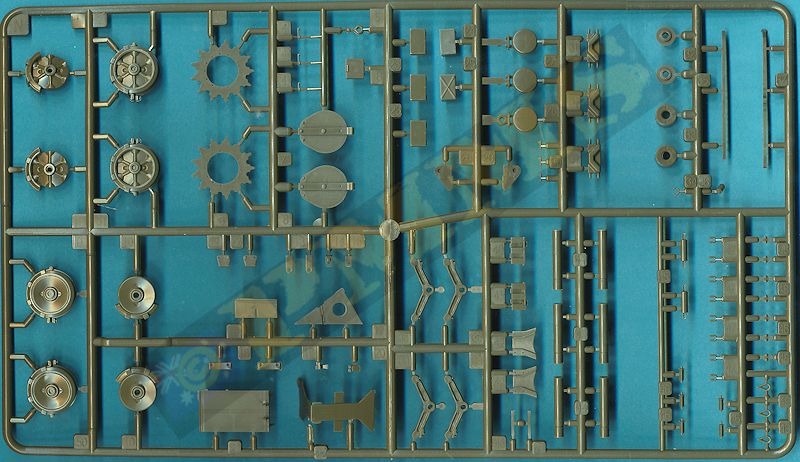

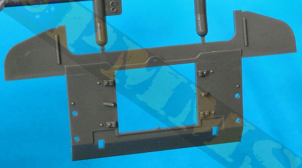
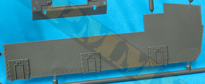
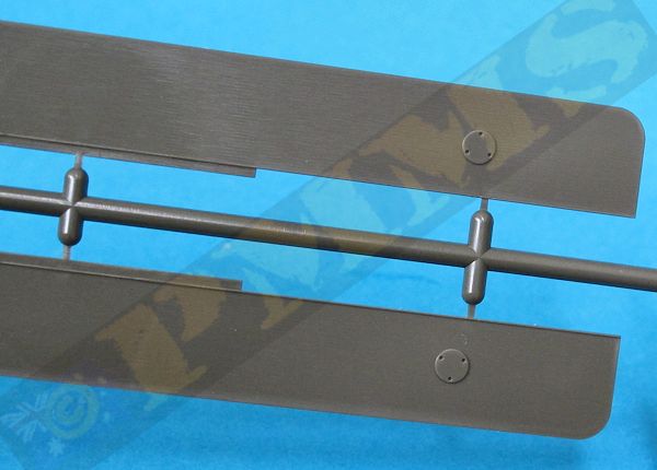
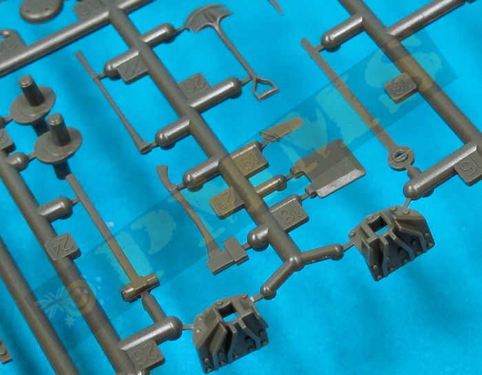
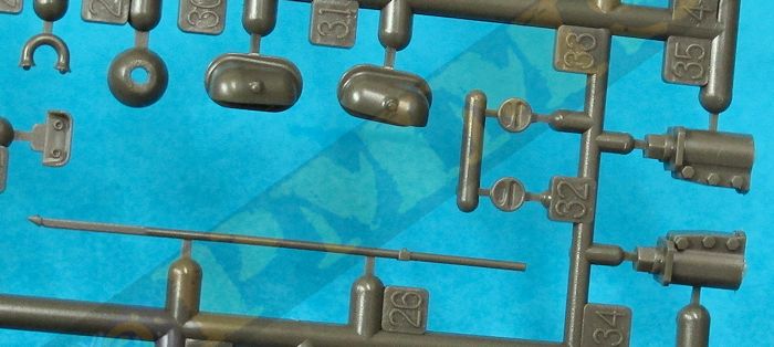
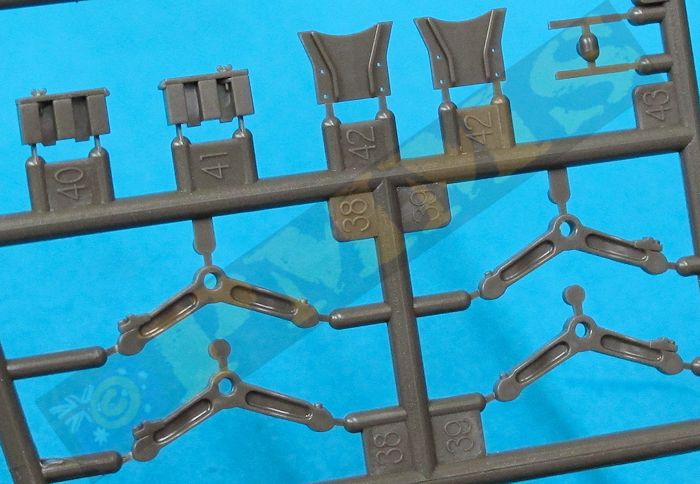
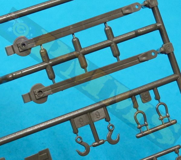
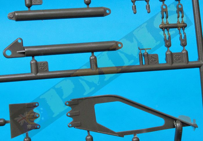
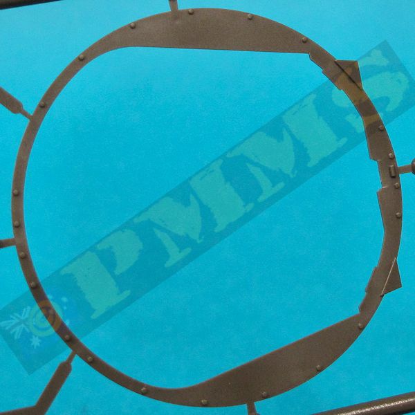
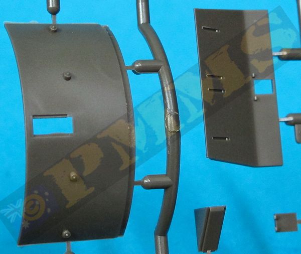
Sprue detail images


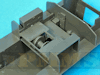
Build images
close new window to return to review
See the Sherman Subject Page for additional reviews of Sherman related kits and accessories.
| SHERMAN R.P.Hunnicutt. Presidio Books  |
Modeler's Guide
to the Sherman Ampersand Publishing  |
U.S. Tech manual TM 9-738 M32, M32B1, M32B2, M32B3, M32B4 Easy 1 Productions CD T042  |
| Heavy Wrecker Ampersand Publishing.  |
Allied-Axis No.11 Ampersand Publishing.  |
Thanks to Tasca Modellismo Co.,Ltd. for the review kit.
