
Faun SLT-56
Tank Transporter
Kit Construction
Step 14 to 19: Rear Tractor Assembly (1)
by Terry Ashley
Step 16 and 17: Rear fender assembly:
The two rear fenders on the tractor are separate parts attached to the chassis
with two large supports each as they are on the real thing.
The added details on the upper side is quite straightforward to assemble with
clear parts for the taillights and mud flaps in etched metal with embossing
and the FAUN logo included.
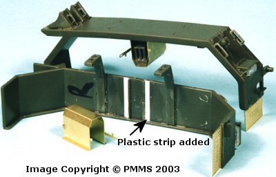
The underside centre Jerry Can racks are also provided in etched metal (parts
PE14) but unfortunately the fit and the size of the etched parts raised a few
problems.
Firstly take note of the directions required for the metal mends (all with
engraved bend lines), the four centre bends are done inward in the direction
of the engraved lines while the two end bracket bends are bent away from the
engraved lines. You can use the supplied Jerry Cans (parts C31, C37, C38) as
a guide to the right size of the finished rack. Unfortunately when you have
bent the rack to shape the two raised attachment guides on the underside of
the fenders are slightly too wide and you will have to trim a little off the
outside of each guide for the etched racks to fit.
The two end brackets on the etched racks are also too wide when bent to fit
and will need minor trimming and lastly the height of the rack isn’t
enough for the Jerry Cans to be inserted after attached to the fender, they
are after all supposed to able to be taken in and out. To remedy this, trim
the moulded on locating brackets and add a small length of plastic strip to
the fender underside to “lift” the rack a little to allow the Jerry
Can to slip in after the racks were attached to the fender. The etched bracket
at the front and rear of the jerry can racks will need to be trimmed to fit
the altered width and after attaching the rear bracket I left the front one
unattached until after adding the jerry can later.
I attached the large fender supports (parts C6 x4) to the underside of the
fenders and allowed to dry before attaching the fenders to the chassis as this
makes it easier but ensure the supports are lined up squarely on the fenders
before the glue dries to ensure a good fit to the chassis.
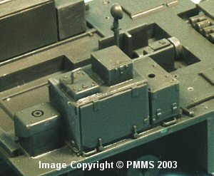
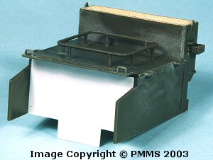
Step 18 and 19: Radiator and air cleaner assembly: [pic 015, 016]
The large radiator/engine compartment assembly was straightforward as was
attaching the etched top screen and small side fittings. The rear of the
engine compartment is open and I decided to blank this off with a section
of plastic card, this may not be necessary after all the components are
added to the rear deck as it will be hard to see so basically was just a
personal preference.
I also added the top panel and fittings at this time and not in step 20 as
it was easier to do so while the radiator/engine compartment was separate
from the chassis.
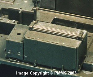
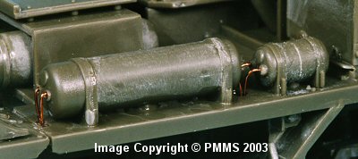
The two big air cleaners are again assembled without problems but watch the
direction of the top caps (parts C55) as the lip faces to the front on each
side.
The two right side air tanks only require the join seams dealt with and the
wires added. Before attaching any of the wiring on the kit I drilled small
holes for the wires as this will allow a more positive join.
Tractor Assembly: Steps 1 to 24.
Step 1 to 5: Cab Assembly.
Step 6 to 10: Chassis and Suspension.
Step 11 to 13: Fuel Tank, Spare Tire and Chassis details.
Step 14 to 19: Rear Tractor Assembly (1).
Step 20 to 22: Rear Tractor Assembly (2).
Step 23 to 24: Adding hoses and piping.
Trailer Assembly: Steps 1 to 14.
Step 1 to 5: Deck underside and Suspension.
Step 6 to 7: Gooseneck Assembly.
Step 8 to 10: Final Deck Assembly.
Step 11 to 13: Ramp Assembly.
Step 14: Attaching Trailer to Tractor.
Return to the first look review of the kit.
Page updated 14 September 2003