
105mm Howitzer M2A1 & Carriage M2A2
1:35 Kit Comparison
Review by Terry Ashley
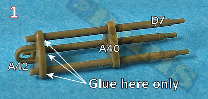
A couple of issues to note, the three retaining rods (parts D7) are slightly oversized and the smaller inner springs should have the coil in the opposite direction to the outer spring but both kit springs have the same direction coil.
After the part cleanup assemblies goes a bit like this.
- Glue the three outer shafts (parts D7) to the front bracket (part A42) using the middle bracket (part A40) unglued as a guide to aligning the shafts, let dry completely. Note: the oblong hole in the middle bracket (part A40) should be aligned vertically with the U fitting on the end bracket (part A42).
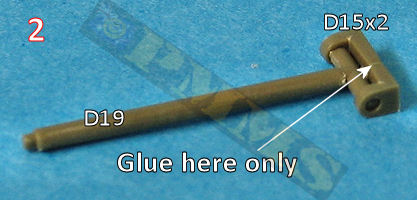
- Attach the two end supports (parts D15) over the end T section of the central shaft (part A19) ensuring the end supports are free to move, let dry completely.
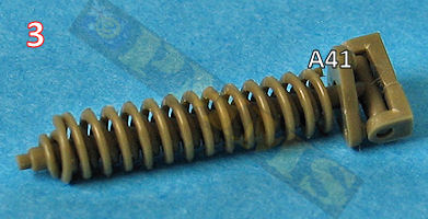
- Slip (don't glue) the small equilibrator spring (part A55) inside the larger spring (part A45) and then slip (don't glue) the rear bracket (part A41) and the springs over the central shaft (part A19).
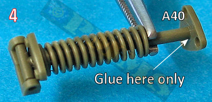
- Use reversible tweezers to hold the springs parts back to avoid gluing the wrong parts together. Glue the end of the central shaft to the middle bracket (part A40).
You must also make sure the bracket (part A40) is perfectly square with the T section of the central shaft (part A19). This alignment is critical for the final fitting of the assembly.
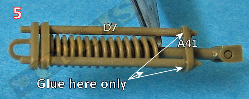
- Again using a pair of reversible tweezers to compress and hold the springs away from the end bracket (part A41), glue the ends of the three outer shafts to the end bracket (part A41) making sure not to glue the bracket to the central shaft. Let dry completely before removing the tweezers.
Again, make sure the brackets (parts A40, A41, A42) are aligned perfectly square with the T section of the central shaft (part A19).
- Once the glue has completely dried on the assembly you should be able to draw the central shaft out compressing the springs which is what happens during barrel elevation.
- The Spring Equilibrator assembly is then trapped between the carriage parts (A60, A61) ensuring not to glue the eye on the bracket (part A42) to the carriage in the process.
The assembled spring equilibrator and its mounting are attached to the top carriage base along with the right elevation arc and traverse arc and as these parts are all quite small the usual care is needed.
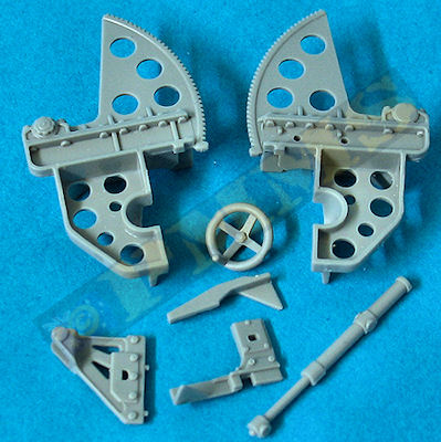
The top carriage has the revised shield mountings as well as the later traverse mechanism with separate hand wheel and shaft that allows you to traverse the gun if required while keeping the traverse mechanism properly aligned. The mechanism attachment brackets have excellent detail definition and again the two part bracket allows the cylinder to move if need be?
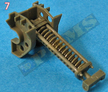
![]() (Step 1,2) The spring equilibrator assembly is moulded in one piece and very simplified lacking any real detail definition especially with the double springs which really aren’t distinguishable at all. The three retaining rods are the right diameter but the assembly is fixed at about 25 ° elevation which limits the accurate depiction of the gun in any other configuration.
(Step 1,2) The spring equilibrator assembly is moulded in one piece and very simplified lacking any real detail definition especially with the double springs which really aren’t distinguishable at all. The three retaining rods are the right diameter but the assembly is fixed at about 25 ° elevation which limits the accurate depiction of the gun in any other configuration.
If you wish the gun to elevate then you shouldn’t glue the central equilibrator rod (part A9) to the spring equilibrator (part A38) or the spring equilibrator to the small attachment bracket (part A32) on the bottom carriage, this will allow some movement but as mentioned not accurately other than the 25 ° elevation.
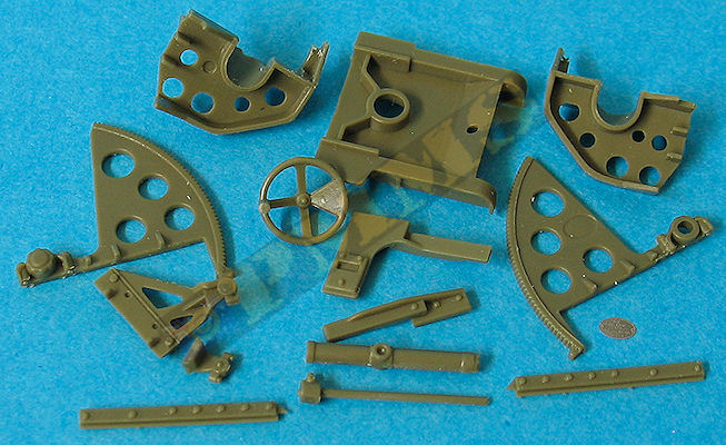
The two halves of the top carriage (parts A28, A41) have the upper elevation arc and the lower carriage moulded together with the addition of the small shield mounting brackets. These brackets are actually too short by about 1.5mm meaning the angle of the small shield is incorrect if fitted as indicated but by adding a small plastic strip spacer to the ends of the brackets the shield should sit correctly when fitted later.
The one piece mouldings do make assembly quite simple but detail definition is compromised as a result such as the bolt heads on the arc mountings that blend into the arc itself lacking definition as does the traverse mechanism assembly on the left side.
The instructions show to attach the elevation arc/carriage parts along with the delicate elevation hand wheels and connections to the gun carriage halves (parts A13, A43) before joining the carriage halves together but this is really not a good idea and leaves parts open for damage as well there is the central join seam on the carriage to deal with. It is best to assembly the gun carriage first before adding the top carriage and other smaller details.
Top carriage parts
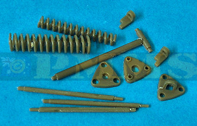
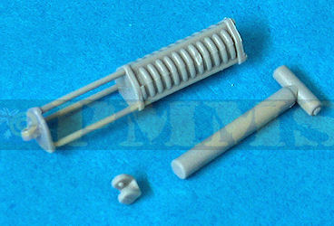
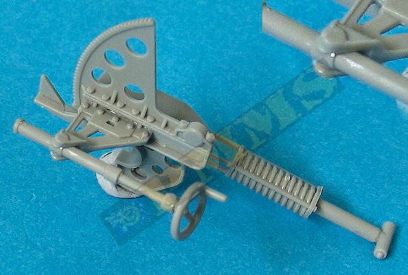
Spring Equilibrator parts.
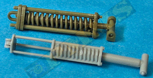
Obviously more assembly is required for the AFV Club Equilibrator but the resulting detail is far superior as well as being fully workable than the DML Equilibrator.
A couple of issues with the AFV Club Equilibrator is the three securing rods are a little on the thick side and the central piston a little under sized plus the inner and
outer spring coil should be in the opposite directions with the kit springs having the same direction coils.
The DML rods are more to scale but the springs are moulded solid and fixed at about 25° elevation lacking any real defininition and
are
very poorly done by comparison.
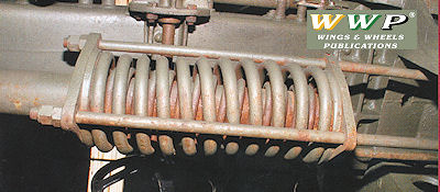
Assembled Equilibrators and image of the real thing for reference.
Reference image from the Wings & Wheels Publications #R 048 - 105mm Howitzer
in detail book showing details as indicated
Assembled top carriage, note the second elevation arc should not be glued until fitting the gun cradle into the trunnions.
The detail on the traverse mechanism bracket is better defined on the AFV Club parts as are the bolt heads and other detail.
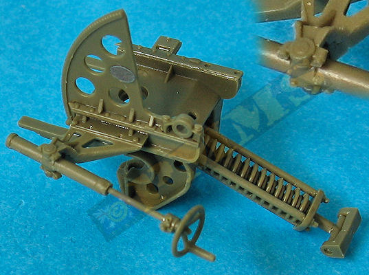
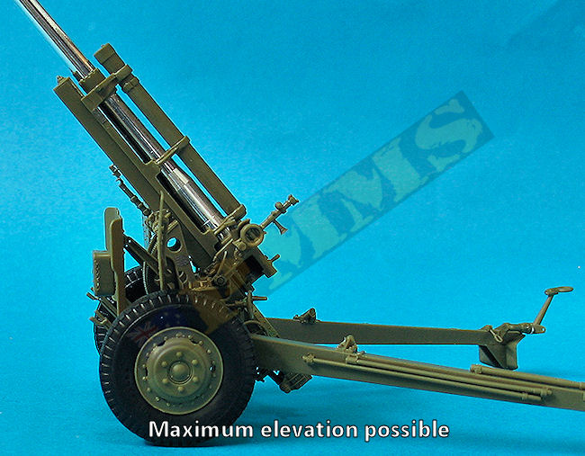
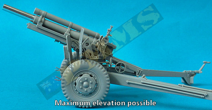
Images showing the maximum elevation of the kits due to the spring equilibrator engineering as mentioned above.
| to Chapter 2: Gun Cradle: |
