
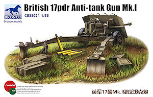
British 17pdr Anti-tank Gun Mk.I
Bronco Models 1:35 Scale Kit No. CB-35024
Kit review by Terry Ashley
Royal Ordnance factories received an order for 100 prototype guns and a small production line was set up. But with the appearance of the German Tiger tank in the Fall of 1942, -efforts were speeded up. As the gun was ready before the carriage, the first weapons were mounted on the 25 Pounder carriages. These entered service in North Africa in February 1943.
Later that year the guns were being produced on their own split-trail carriage. The 17 Pounder was built in seven marks (Mk.l to Mk.VII) each with minor changes to the gun breech or mounting. The 17 Pounder Anti-Tank Gun was the most powerful weapon of its class to see action in WWII. It was of 76.2mm (3 inch) caliber and could fire an APCBC shot at a muzzle velocity of 2,900 feet per second, this could penetrate 140mm of armour angled at 30 degrees and at a distance of 1,000 meters.
This was more than enough to deal with Tiger and Panther tanks at battle ranges. In the Summer of 1944 the APDS round was introduced, this had a velocity of 3,950 feet per second and could penetrate 195mm of armour at 1,000 meters. A HE shell was also developed for the 17 Pdr, the initial rounds were not successful, but later rounds with reduced propellant charge were highly effective. Great efforts were made to get the 17 Pounder mounted in armoured vehicles, the most notable being the Sherman Firefly of which 2,200 were produced. Other tanks to mount the weapon were the A30 Challenger, A41 Centurion, and the A34 Comet had a 17 Pdr derivative. Self-Propelled Tank Destroyers included the M10 Achilles, Valentine Archer and A30 Avenger.
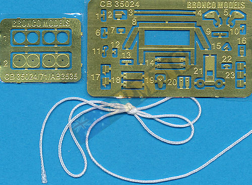
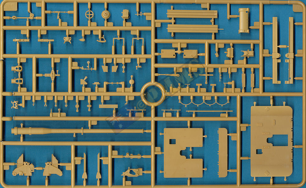
The standard of moulding is excellent with clean crisp detail and only some very minor flash on a few parts and all but a couple of pin marks hidden after assembly. There are a couple of small sink marks that are hardly noticeable but will need filling along with some very small and finely moulded plastic and etched parts that will require extreme care when removing from the sprues and during assembly.
The kit is broken down in to sub-assemblies which come together for final assembly and some are quite intricate due to the number and size of the parts but with care there shouldn’t be any problems?
Make sure you work well over your workbench as the dreaded carpet monster will have salivating jowls with the smaller parts in this kit. There are also the usual mould seams and the many plastic nodes to be cleaned from the part before assembly.
I don’t have any actual 1:35 plans of the gun to check dimensions but the kit details match available reference photos very well.
Also trapped between the breech halves is the lower block actuating bracket which moves in conjunction with the breech block and side mounted lever so make sure you don’t glue the bracket (part A37) or the lever (part A35) to the breech itself if you want this to be moveable?
You should ensure the mating surfaces of the two breech halves are smooth as there were a few small imperfections to be smoothed out on my parts but other than that the assembly was delicate but trouble free.
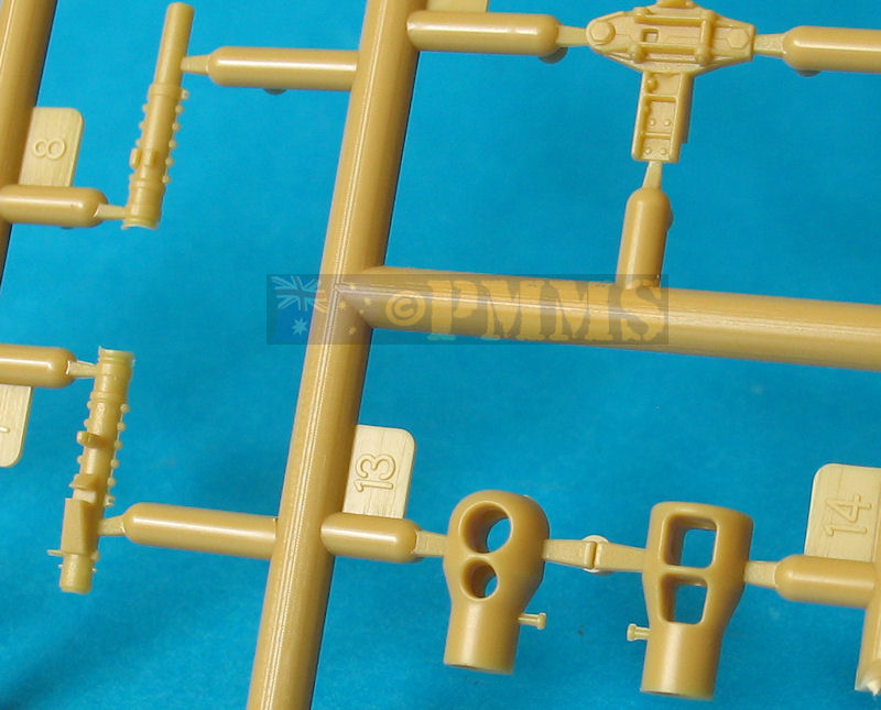
The main gun sight and mounting is another very intricate and delicate assembly with some very small plastic and etched parts but other than the care needed during assembly there were no other problems. The same goes for the barrel top cover which again has some small parts needing care but these parts add considerable detail definition to the assemblies.
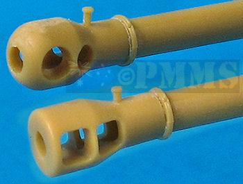
The barrel tube is in one single piece and apart from the fine mould lines to eliminate there is no other cleanup with a choice of two one piece muzzle brakes both with the bore and side gas holes cleanly opened up.
There is the early rounded profile and later stub nosed profile muzzle brakes and you can fit these depending on your choice as both appear in wartime images of the 17pdr in action. The contours of both match available images well although the top locking nut appears a little oversized.
The barrel sits on a two part slide with end brackets that the barrel sits on and you needn’t worry about the side join seems in the slide as these are hidden inside the gun cradle after assembly. The cradle is in two halves that fit together well with additional underside braces and toothed elevation arc.
Fitting the sub-assemblies of barrel/cradle/breech, top cover and sight are all straightforward but test fit before hand to see if any minor trimming is needed, I did have to trim the locating lug on the sight mounting to get a snug fit but the remaining items all go together well. Just take care as there are some quite intricate assemblies here with the overall assembly being very detailed.
One thing to note is the barrel tube is hollowed out to a depth of 35mm at the breech end which allows you to insert a full round into the chamber as well as close the breech block with the round in place should you wish to build an action diorama for a nice realistic appearance.
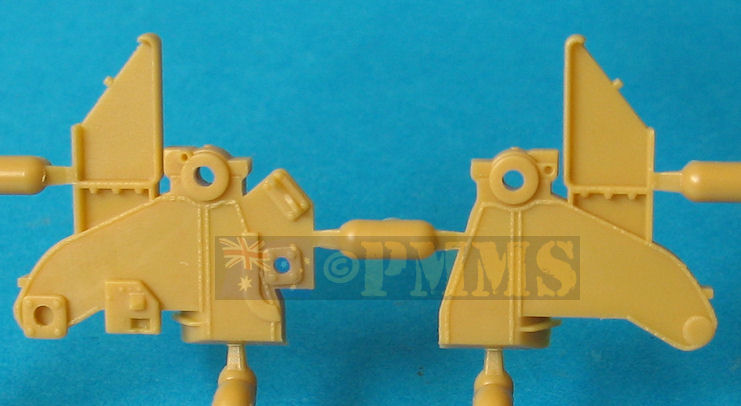
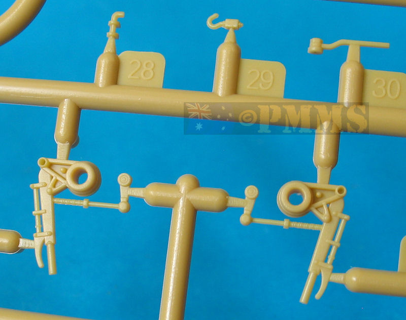
The two gun trunnions have well defined detail on both sides with additional multi-part traverse and elevation assemblies on the left side; these again have some quite small parts requiring care with assembly. There is a small two part traverse sprocket that fits into a recess between the bottom of the traverse hand wheel assembly and the trunnion but this recess wasn’t fully hollowed out on my kit and I trimmed the sprocket pin accordingly to fit.
There are a couple of bolt heads to be cut from sprue A to add to the top of the trunnions which shouldn’t be a problem?
The only pin marks needing attention on the kit are on the inside of the shield mounts on top of the trunnions and as these are quite shallow they are easy to remove with light shaving with a #11 blade.
Trapped between the two trunnions is the small elevation sprocket with housing (part A53) and you also get an option of a toothed sprocket wheel (part A71) with etched brass housing. This requires some careful bending of the brass to enclose the sprocket within the brass housing, but after the effort this housing was too big and wouldn’t fit in place as there wasn’t enough clearance between the sprocket and the elevation arc so it’s best to save yourself some effort and just use the plastic sprocket.
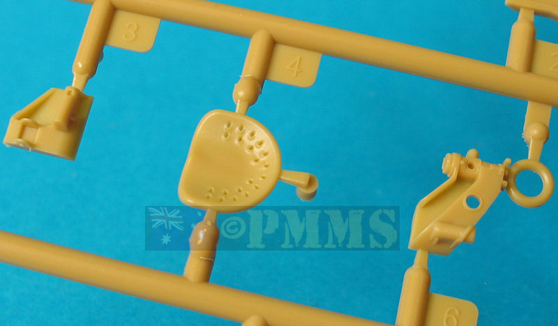
The trunnions are glued to either side of the lower base to which is also attached the Gunner’s seat and support frame. The gun is able to elevate or depress after assembly but not by a lot as the actual gun only had a range of +16.5° elevation and -6° depression.
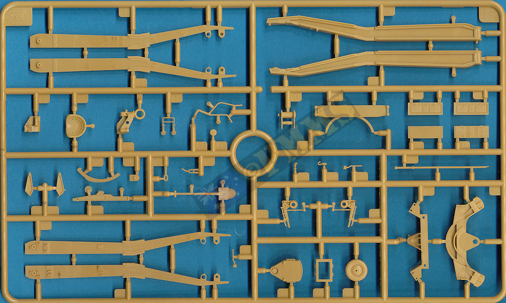
The three part spades can be attached so they can be moved from the deployed to stowed position by way of the rotating locking bolt (part C8) providing you are careful with the glue during assembly. The locking bolt works exactly like the real thing and makes for very realistic movement of the spades allowing you easily change their position. Care is needed gluing the bolt lever (part B30) to the bolt as the locating point is not that solid and I drilled a hole to insert a short length of 1mm wire to strengthen the join, but if you are going to glue the spades in position this wouldn’t be necessary.
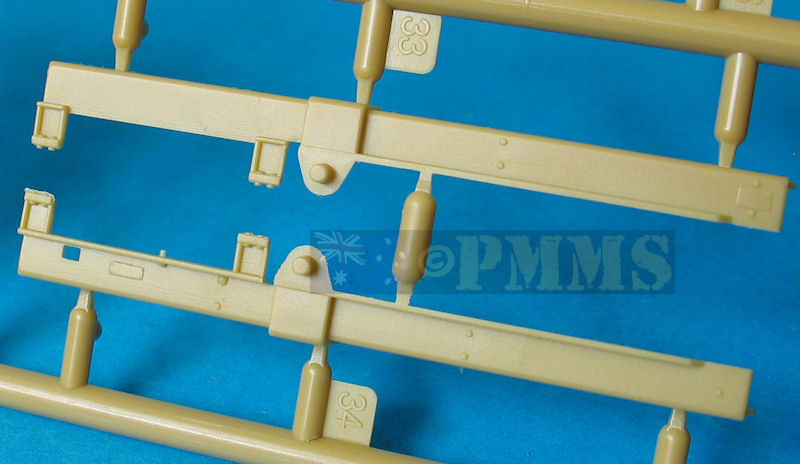
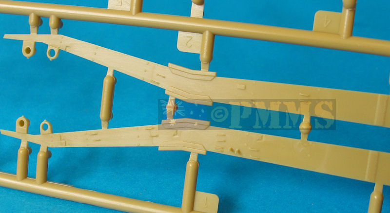
There are numerous small etched and plastic brackets and fittings added to the trail arms as well as the rear locking brackets used to secure the trails in the travel position with all these going together without any problems.
The kit also includes a small caster wheel that can be attached to the rear of the left trail arm but photo evidence suggests this was seldom fitted so unless you have an actual photo showing the wheel fitted it’s best to leave off.
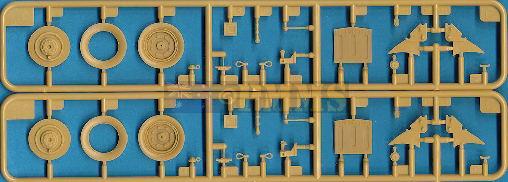
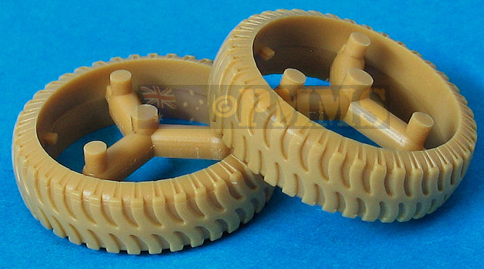
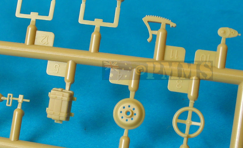
The outer sidewall section (part C3) also includes the wheel rim with excellent bolt and rim detail definition while the sidewall section has the ‘Dunlop’ and tyre data legible for a good appearance. It’s best to fit the outer rim/sidewall section to the main tyre first and make sure the join is perfectly flush and allowing this to dry before proceeding.
The central disc section with inner hub detail (part C1) is trapped in place by the rear sidewall section (part C1) allowing the wheel to rotate once attached the carriage axle. I needed to reduce the diameter of the central disc slightly to allow the wheels to rotate freely after assembly.
Added to the inner hub is a nicely detailed brake lever and hub and you should ensure the wheel assembly is attached with the brake handle towards the front as it’s easy to fit this at any angle if not careful.
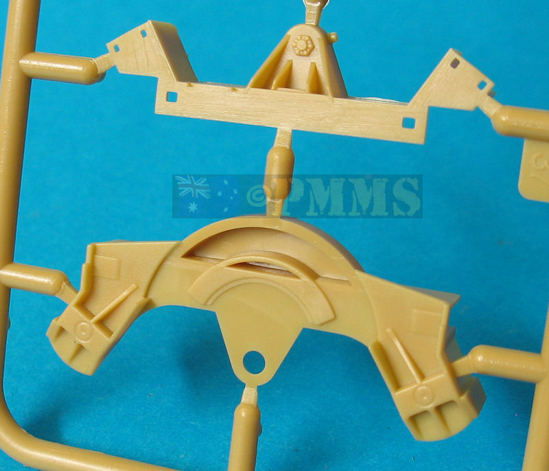
The lower carriage has two main parts, the top section (part B38) and the lower section (part B37) with the front traverse guides (parts B15, B20) and the underside bracket (part B12) and it's important for the assembly order of these parts to be correct for the easiest assembly. See image guide to this assembly as outlined below.
There is a bit of cleanup needed on these parts, more than the rest of the kit put together really. Firstly you should ensure the bottom surfaces of parts B37, B38 are smooth as they are bit rough in my kit and needed smoothing out. Part B15 has a guide channel on the inside curve for the lip on base part B34 to slip into but the channel had a raised bit of plastic partly blocking this that had to be removed before assembly, a little messy unfortunately.
Firstly fit the top locating pin on each trail arm up into the recess in the top section (part B38) and then glue the lower section (part B37) into place ensuring you don't accidentally glue the trail arms. You must also ensure the central holes for the gun assembly are perfectly aligned or you may have problems fitting the pin in the lower carriage into place?
You then fit the two axle stubs (parts C10) into the part B38 recesses (note direction of axle stub) and secure with underside bracket (part B12).
The circular front of the carriage (part B15) has the traverse teeth arc (part B20) added to the outside but the right side locating hole had to be opened up a bit to accommodate the pin on the arc.
The upper carriage/gun assembly now has to be fitted at the same time as you attach part B15 to the lower carriage as the lip on the front of the upper carriage base (part B34) has to fit into the guide channel inside part B15 as you fit this to the lower carriage. Care is needed as there is not a lot of room to work with the trunnions already attached to the base part B15 but once all is assembled the gun can traverse left or right as per the real gun. The actual traverse of the 17pdr was 30° left and right which was quite useful.
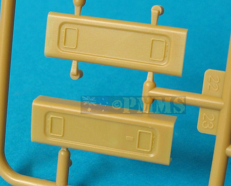
The surface detail on the shields is well done with rivets, hinges and tie downs included as well as the correctly depicted spacing supports for the front plate which is easily fitted in place due to a series of pins along the top with corresponding holes on the back of the spaced armour.
The lower folding plate has two etched securing brackets for good definition as well as the top hoops and rear detail. There are two curved etched brackets on the back of the shield which you have to bend to shape but for some reason there are two engraved lines on one side of the brass strips which makes adding the curve difficult as it wants to bend at the engraved line, a bit annoying really as it takes more effort to get these bent to the correct curve due to this.
Fitting the shields to the gun carriage is quite straightforward by firstly attaching to the large brackets on top of the trunnions while resting on the brass supports on the lower edge of the trunnions, these may need minor adjustments to align to the shield angle.
The two outer support arms (parts A60, A61) are then easily attached and the assembly is basically done.
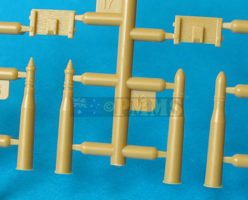
The detail on the rounds is nicely done and matches available info on the different ammunition types.
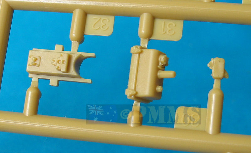
Also included are two sizes of steel ammo cases and two sizes of wood ammo boxes with the wood boxes in six parts with additional 'rope' handles with the fit being very good resulting in nice looking boxes. You can add the rounds provided (APC and APDS) and leave the lid off or assemble the boxes closed leaving the rounds free for other uses.
The metal cases are in two halves with etched and plastic end caps with good detail but the instructions show to add the rounds into the cases before gluing the 'top' on. These cases were actually solid units with the rounds extracted by removing the end caps so you can save the rounds for other uses and just glue the case halves together, sanding smooth the join after the glue has dried.
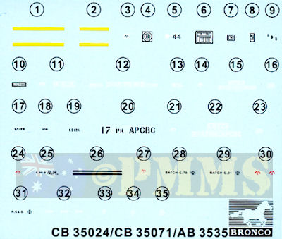
There are colour illustrations showing the ammo colours as well as the boxes in overall No.15 Olive Drab.
The instructions are the usual exploded view drawings that are easy to follow in the main but there are some quite busy sequences so careful study of the illustrations beforehand will avoid any problems. A couple of small bloopers to note are at step 7 with the ammo box parts numbered C13 and C17 when in fact they should be B13 and B17 but other than that everything match up fine.Option 1:
Overall British No.15 Olive Drab.
 |
There are some very small parts and quite busy assembly sequences especially with the upper carriage/gun and lower carriage and care will be needed with this kit not really being for the inexperienced modeller.
But despite the few issues outlined above the overall appearance of the assembled gun is one of quality and attention to the finer details resulting in an outstanding model IMHO
Rating 9/10
Click on thumbnails for larger view

Detail and assembly images
Sprue detail images


| British Anti-tank Artillery 1939-45 Osprey New Vanguard 98  |
The 17-Pounder Anti-Tank Gun in Canadian Service Service Publications  |

 and
and 