

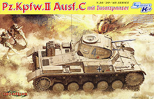
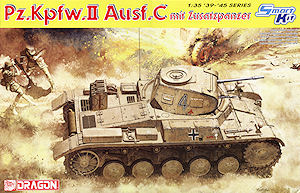
Cyberhobby/Dragon have followed the recent kit of the Panzer II Ausf.F (kit#6263) with this kit of the earlier Panzer II Ausf.C and again the kit comes labelled Cyberhobby in some parts of the World and Dragon in others depending where you live but is the same kit in both.
The kit captures the overall features of the Panzer II Ausf.C fairly well but there are some issues due to parts carried over from the Ausf.F kit not being applicable to the Ausf.C but the overall kit dimensions measuring up well to available data with a few discrepancies. There were some differences between the 1:35 plans in the books listed below which made things tricky and again shows again you can’t bet your house (or kit) on a single set of commercial plans.
The main areas of concern are with the running gear and one in particular with the drive sprocket which also applies to the previous Marder II (kit #6262) and Panzer II Ausf.F (kit#6263) I missed at the time. Basically the sprocket has one less tooth than it should and at the time I only checked the diameter but not the number of drive teeth so I apologise for that but more on that later.
The other is the absence of the rear smoke grenade rack which is seen an most Panzer II Ausf.C such as those in Norway, France and especially with the DAK, which means three of the decal options in the kit are suspect without the inclusion of these racks. It should be noted that the later armoured box smoke launchers are still included from the previous Ausf.F kit but these are not applicable to the Ausf.C as they are a different design on the earlier vehicles mounted on the exhaust and not the rear hull.
Left over from the Marder II and Ausf.F kits are the optional parts such as the standard Panzer II drive sprocket and the reinforced drive sprocket used exclusively on the Marder II and Wespe so you have to watch to use the correct one here as the instructions just give you the option of either which is incorrect. There are still the three types of idler wheels supplied from the previous kits plus a new earlier sprocket for this kit and the others can be consigned to the every growing spares box.
New parts for the Ausf.C include a new lower hull tub and upper hull plus new earlier suspension bogies and idler as mentioned along with the road wheels, tracks, interior parts and track from the previous kits.
As Tamiya have just released their version of the Panzer II Ausf.A,B,C comparisons are inevitable but thankfully both are not the same version so avoid the direct duplication of effort we see all too often unfortunately. The Cyberhobby/Dragon kit represents that later modified Ausf.C with turret commander’s cupola, additional hull and turret armour and revised rear deck details while the Tamiya kit is the early Ausf.c A, B, C with the twin hatch on the turret and earlier engine deck features. It also includes the additional hull and turret armour as well as the rear smoke discharges missing from the Cyberhobby/Dragon kit.
As such I won’t make a full comparison but just compare images of some key areas common to both types along the way to give and idea of how each shapes up but as mentioned being different version you can happily buy both with a full review of the Tamiya kit to follow shortly.
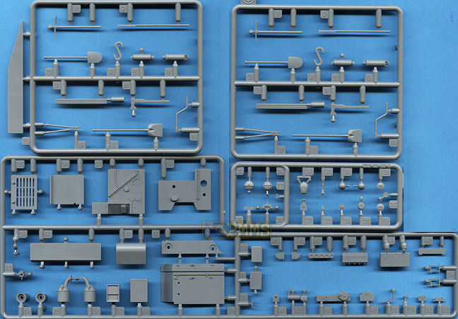
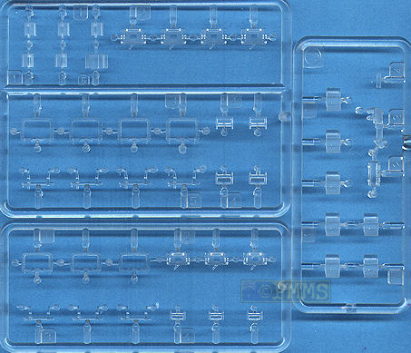
The kit consists of 480 parts in light grey plastic, 44 parts in clear plastic with three etched frets and three wire grab handles, a formed brass shovel bracket plus individual link “magic track” and a single decal sheet.
Standard of moulding is again excellent with the heavy use of ‘plastic nodes’ on the parts which helps keep pin ejector marks to a minimum but will take a bit of effort to remove in some cases. There is the usual fine moulding seams on the parts to remove but nothing really out of the ordinary for plastic kits but you should watch as some of these mould seams double as actual seams on the real parts such as the road wheels and bogies arms.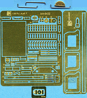
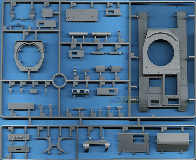
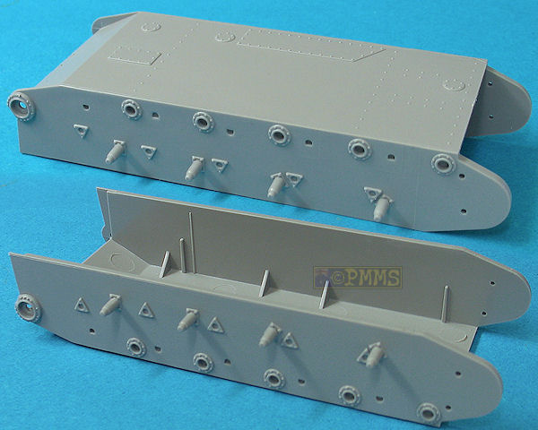
This is a conventional plastic tub which has quite thick sides with internal bracing fillets and includes raised detail on the sides for the suspension mountings and access plates on the bottom with separate front and rear panels to make up the full tub. The sides on my tub were bowed in a little towards the centre of the hull and this affected the alignment of the final drive housings slightly although this is all but hidden when the upper hull is attached.
There is no other detail on the tub sidewalls and fitting some of the additional internal parts is hit and miss as there are no locating tabs or lines provided so you have to line these up by eye after adding the floor and engine bulkheads.
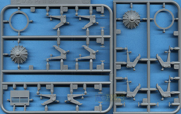
The four return roller mounting posts on the Panzer II are not level but on a downward angle with the rear post being lower than the first and the kit captures this feature precisely for good attention to detail.
Each axle/spring assembly is made up of two parts each, the bogie arm, axle and upper spring all in one with a small top bracket that will need care removing from the sprue with the bogie being the correct type for the earlier Ausf.C. You have to take care as the forth bogie assembly is different from the first three as indicated in the instructions plus there are additional small arm bump stops added to each side.
The mould seam lines down the centre of the springs will need care during removal to ensure the definition of the springs is maintained but the springs face downwards after assembly and the seams may not be that noticeable if not cleaned up.
On the other hand the mould seams on the axle arms can be left in place to simulate with central weld seam of the actual arm with care needed when cleaning up the sprue attachment bur to preserve the seam at this point.
There are a couple of issues when fitting the rear idlers, the first is the instructions don't identify the separate idler axles with the illustration just showing them in place without any part number indicated which is actually parts G4. These axles are offset which allows you to alter the position of the axle post and in turn the height of the idler wheels.
The other issue is the idler sits too far outboard and does not line up with the road wheels which will effect the fit of the tracks and you will have to modify the axle stub by shortening it 1.5mm to allow the idler to sit further inboard in line with the road wheels.
The lower front plate is a single piece with the correct lower curve and this fits between two brackets that fit to the front of the hull tub sides to form the final drive reinforcements and some care is needed fitting these parts. The front plate must be positioned between the two side brackets while you fit the brackets as it will not fit in afterwards and as there is no locating guides for the brackets these have to be aligned manually level with the hull side plates.
The brackets were fractionally thinner than the hull sides meaning there is a slight step between the two after assembly which will need attention but this is partly hidden by the final drive housings as is the join seam at the top of the brackets that also needs filling.
The final drive housing is a separate part with four small bolt heads moulded onto the sprue runners which you have to carefully cut off and attach to the final drives in four places and care is needed when cutting the bolts from the sprues so they don’t take off into the void. There is a problem here as the final drive housings on the earlier Ausf.A,B,C where a different more rounded and bulbous housing much different from those in this kit which are applicable to the Ausf.F and later types. There is little you can do about this but I guess most of the housing is hidden behind the large drive sprocket and tracks after assembly in any case.
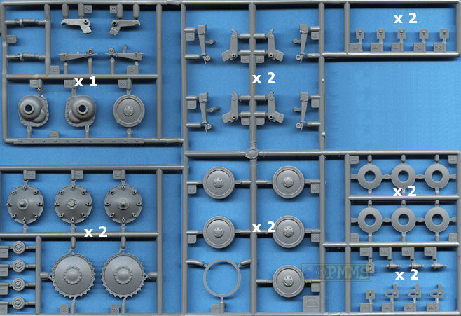
As mentioned there are alternate drive sprockets, the standard Panzer II type (parts E2) and the re-enforced type used exclusively on the Marder II and Wespe (part E3) and the instructions only show both with the option of using your choice. This is incorrect as you can only use part E2 on the Ausf.C with the other sprocket used on the Marder II and Wespe as mentioned and it really is a pity that with all the research we hear about the instructions couldn’t tell you this simple fact to avoid confusion?
There is another major issue with the drive sprockets supplied in that they only have 25 drive teeth when the actual sprocket has 26 drive teeth and as mentioned this issue applies to the earlier Marder II and Panzer II Ausf.C also as they use the same sprockets. Again there is little you can do about this other to live with the incorrect sprockets unless someone want’s to make resin replacements with the 26 drive teeth.
All the 1:35 plans in the references below show the 26 teeth and on checking any suitable side on photos of the Panzer II (and other types) confirms the presents of the 26 drive teeth and hopefully this will be fixed at some stage?
Despite this issue the sprockets feature well defined bolt details around the rims and also have the bolts around the inside of the sprockets. There are some shallow pin marks on the insides which are very easy to remove as they can be seen after assembly with the sprockets designed to be glued to the final drives.
The road wheels have the outer wheel and tyre with a separate insert for the back to eliminate the hollow look and the wheels feature excellent details such as the weld beads around the outer rims with “Continentau” and tyre data embossing on the rubber sections. Also included is the raised seam around the middle of the rubber section which is evident on newer wheels but the attachment points to the sprues means there will be two scars in the seam line, one of which can be hidden at ground contact but the other is evident. If you take extreme care and some nifty knife work when removing the excess plastic from the sprue attachment you can preserve the raised seam line so the scar is less evident.
The return rollers again have nice details of weld beads and embossing with the raised tyre seam and the same comments apply here as with the road wheel but both types of wheels are very well done and look very good with careful painting bringing out the detail.
At the back is the new Ausf.C style idler wheel made up of three parts, the inner wheel disc, the outer disc rim and the outer thinner rim lip with the disc also including the two small holes seen on some idlers. There is a small issue with the idlers in that all the 1:35 plans available show the diameter of the idler as 18mm in 1:35 scale but the kit idlers are 19mm in diameter but I don’t have the actual diameter measurement for the idlers to confirm this. For some reason all the references list the diameters of the road wheels and return rollers but not the idlers?
Also included are the three different pattern idlers from the previous kits and thankfully the instructions don’t offer these as alternatives and you can just add these to the spares box.
The rear panel has separate detail for the tow pintle, tail light and four part exhaust with a separate etched heat guard which you have to bend to shape to fit and annealing the part beforehand will help with this. For some strange reason the smoke grenade rack normally mounted on the exhaust brackets is not provided and this really does limit the use of this kit much like the same issue with the first Panzer IA kit release with most photos of operational Panzer II Ausf.Cs showing these grenade racks, most notably those used by the DAK. With three of the decal options proving markings for DAK vehicles you will have to source the racks elsewhere if you want to build an accurate model?
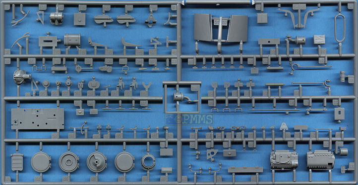
The interior like the previous kits gives you a fairly comprehensive interior with the transmission assembly is in ten parts that goes together without any problems with the brake drums in multiple parts with good details added into the lower tub as are with additional gear levers and the driver’s seat, with fine tread plate pattern for a very busy interior. Notably the instructions don’t show to fit the driver’s foot pedals as with the Ausf.F but the pedals are still in the kit if you wanted to add these yourself?
The side engine bulkhead is in five main wall parts with additional smaller items and the main parts fit together without any problems as do most of the smaller details but watch the parts J37, J38 as there are no locating pins for these and you have to cut off a couple of small bolt heads for part J38 to sit flush.
The two part air cleaner has additional etched mounting brackets added but watch the lower bracket (part MA30) as this has to be bent “away” from the engraved bend lines and not “into” them as is the normal procedure for etched parts. If you bend these the “wrong” way they will break off when bending back the other way due to the thin metal so ensure you bend them the correct way first time, which is with the triangular indent for part MA25 facing outwards.
All the sub-assemblies go together without any real problems and also fit neatly into the lower tub and of course there is scope for adding finer details for those wanting the detail up the kit further.
The small equipment boxes and radio located on the tub side walls have straightforward assembly but need care when fitting as the locations are not marked as mentioned and fitting after the floor has been added should make it easier to line up.
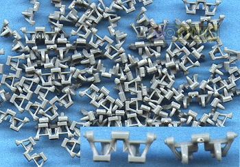
Included is a set of individually moulded “magic track” with the only cleanup being a very small moulding scar on the inside of each link which really doesn’t need cleanup if you don’t want to.
The detail on the links is very good with nice face detail and hollow shell effects on the guide horns with the use of slide moulds and the links are designed to be glued together but are not workable.
Fitting the links together is quite easy as they simply intermesh but are fairly small and slippery especially when getting them to form around the drive sprockets and idler wheels. The best method is to apply a small amount of liquid cement to each link and wait for the glue to start and “go off”, you can then form them around the sprocket and add track sag easier then if the links are loose.
The assembled track runs look very good with the instructions indicating there are 99 links per side.
The new upper hull is in one piece including the fenders with cut-outs for the engine access hatches and turret ring as well as the separate glacis plate with separate access hatch as well as the front and side superstructure panels also separate parts.
Detail on the hull top includes nice tread plate pattern on the fender top sections but with the rear right fender smooth which we now know is how it should look with the undersides of the fenders being plain. There are nicely depicted weld seams and engraved panel lines around the hull and as well as the rear bullet splash guard separate with the front guard included with the hull moulding.
At the front the separate glacis plate has nice flush screw detail at the back and weld seam along the front edge and this fits to the lower front hull panel that has the subtle lower curve of the Ausf.C front panel. The separate glacis access hatch has nice inside details but there is a question on the actual size of the hatch with some plans showing it the size as in the kit while others show it slightly larger with more rounded corners than on the kit part. Actual photos of the hatch seem to indicate the larger size is more appropriate and that the hatch also extends further back into the recess between the plate and flush screw strip than it does on the kit hatch.
There is some fit issues with the glacis as it sits too high on the lower hull brackets mentioned above and you may have to trim these slightly to get the glacis to fit evenly with the upper hull front and this will vary depending on how well you fitted the brackets earlier in the construction, so take care here.
Other front details include the two fender mounted head lights with clear lenses or blackout slit covers plus the Notek light and hatch rest post with just the light wiring needed to finish off.
The front superstructure plate has the driver’s visor as a separate part that can be shown open or closed while the right angled plate visor as a single part with inner visor detail and you can again show this visor open if you wish? On the inside is the driver’s instrument panel that fits to the underside of the hull top and while this will be hard to see after assembly it’s good to see it’s there.
There are alternate front panels, the un-armoured and additional armour panels to be added to the superstructure although only the visor for the armoured panel is provided which were different from those on the unarmoured visor.
The instructions don’t indicate the use of the spare road wheel carried on the glacis of some Ausf.Cs but the spare from the Ausf.F kit is still included so you can add this if you wish?
The forward left side panel has separate outer and inner visors with the fit of the side panels to the superstructure being spot on without any gaps or trimming needed.
Added to the fenders are the various storage boxes and pioneer tools which have separate etched brackets and clips for good detail definition with the four part jack having a choice of plastic or etched mounting brackets depending if you want a quick build or more finer detail.
The engine deck has open intake grills with separate engine access doors and access hatches while there are alternate inner grills and covers that help to eliminate the see-through look but you may want to blank off some of the grills to prevent seeing into the empty engine bay.
A couple of things to watch on the rear deck is the rear grill (part A26) has to be located centrally in the opening with a gap either side but the instructions don't tell you this and it's easy to try and fit this to one side leaving a large gap. You also need to trim away the exposed parts of the inner lip before fitting the grill as this shouldn't show in the opening.
Also the gap around the two engine bay doors is not large enough as these are not flush fitting like many doors and the gap should be about twice the size than on the kit, referring to photos will fully illustrate this.
The right side engine bay doors are also separate parts that can be shown open and while there is no engine details inside it allows you to easily install a resin engine if you wish?
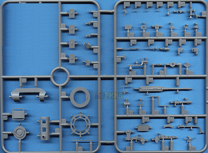
This is basically the same as the Ausf.F kit turret but with some minor alterations such as the weld seams toned down and some minor details changed as well as new parts for the front panels, mantlet and vision port covers.
The upper shell has a separate lower ring and front panels with the gun mounting and has excellent surface details including the roof flush screws and panel weld seams as well as all the vision port covers as separate parts. These too have the correct features with only two having vision slits while all have internal visors made up of four clear parts each for good details.
One thing to watch is the turret front panel (part N1) doesn’t get a mention in the instructions, it’s just not there in one illustration and there the next just to see if you are paying attention?
This part has to be fitted before you add the additional armour (part N34) to the turret.
Also included is the additional armour fitted to the front of the turret but not the appliqué central panel often fitted above the guns on DAK vehicles but this is fairly easy to make from thin plastic card using photos as guides if you wish to add this for the appropriate marking options.
The Commander’s cupola consists of the lower ring with clear periscopes and the upper ring that represent the cupola nicely. Added to this is the cupola hatch which is nicely done and includes all the relevant details such as the central signal port and top support post as well the inner latch as an etched part with about the only nit pick being the inner head pad could do with better texturing.
Fitting the hatch to the cupola ring was little tricky as the hinge is moulded as part of the top ring and a bit of care will be needed to get in place, it would be easier to show the hatch open showing off the interior.
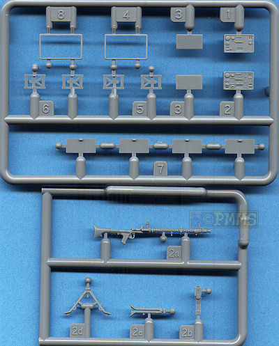
The main 2cm KwK30 L/50 gun is in one piece with the flash suppressor hollowed out using slide moulds although the small suppressor holes are not open but just indentations and you may want to drill these out for a better look. The barrel itself is the correct length when comparing to the available plans but actual photos appear to indicate it is slightly too large in diameter and the flash suppressor has excessive flair. This may not be an issue for many but if you want to address this there is the metal 2cm KwK30 L/50 gun from armorscale (set #B35-027) already available.
The co-axial MG34 is also in one piece and very well done for a plastic gun but note that the gun provided has a number of small fittings along the cooling jacket for the sights, tripod and AA mountings which are not applicable when fitted to the turret mounting and you should cut these off before fitting. Also you have to cut off the stock as this is not fitted to the gun when mounted inside the turret and it would have been nice if Dragon gave you a specific MG34 for the kit instead of just throwing in an infantry gun requiring a bit of work to represent the vehicle mounted gun.
The instructions don’t tell you to remove any of the MG details but the sequence images do show the rear sight removed but not the cooling jacket fittings, you can also improve the look of the MG34 by using the excellent metal barrels/cooling jacket from ABER or Adlers Nest if you wish which will also deal with the additional fittings as mentioned above.
Both the 2cm and MG34 fit to the full gun mounting inside the turret which is quite detailed but you have to be careful positioning some of the smaller parts as the instructions are not that clear on the location and some trial fitting will be needed.
The instructions don’t show you to fit the gun into the two mounting halves (parts B38, B39) as you glue these together but you must do this as it is difficult to fit the gun later and there are a number of other parts that are a bit tricky. You must attach part B14 first to part B38 before fitting part B40 and fitting part B33 is again not clear and more attention needs to be given to these instructions as things are not that clear.
These assemblies attached to mountings on the lower turret ring and the curved front brackets glue to the back of the curved gun mantlet allowing for elevation but this is a very tricky operation and some care will be needed. The two small port covers on the mantlet can be positioned open of closed and the outer front plate fits neatly in place once the mantlet has been positioned.
Other items inside the turret include the traverse gear and the rear Commander’s seat but watch as the turret does not have any locating tabs to hold in place and just rests inside the superstructure opening, this shouldn’t be a problem unless someone turns the model upside down.
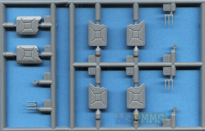
Also included in the kit are three jerry cans with two halves and an inner etched part that form the central seam of the real jerry can and thankfully these parts fit together perfectly unlike the previous jerry cans of this type. Added to the cans are separate grab handles that have a central slit that fits over the central etched bracket along with the filler spout. There is also an etched securing strap for adding the grouper jerry cans to the rear engine deck or anywhere else you wish to use these.
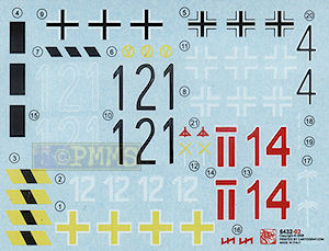
The well printed sheet has markings for seven Panzer II Ausf.Cs although only six are shown in the instructions with a variety of cam schemes from different theatres for some colourful marking options.
As mentioned the three markings for North Africa and one from Norway would need the rear smoke grenade launcher rack added and possible the added armour on the turret and checking references will determine if needed?
The markings included are:
|
|
Overall this little kit from Dragon will build into a reasonable replica of the Panzer II Ausf.C modified from the box but there are numerous issues to deal along the way that require attention if you are concern with accuracy?
There are nice details such as the surface welds and other finer details for good definition but the number of drive sprocket teeth, final drive housings and idlers will need attention as well as some fit issues but if you don't care about these things it will build fairly easily into a nice looking kit.
The lack of smoke grenade racks limits the kits application as some of the decal options can't be built without these just like we saw with the first Panzer IA kit and it’s a shame these aren’t included to “complete” the kit.
The full interior also adds to the appeal and while providing most of the major structures with some excellent detail there is as with any kit there is scope for those wanting to go to town and add all the finer details but the overall impression is of another rushed job that leaves a bit to be desired accuracy wise while also including some nice features.
But having said that it is far better than the old Tamiya Panzer II or the Alan Panzer II kits and if the issues mentioned above don't bother you and with a little work a good looking kit will result.
As with previous Dragon kits you really do have to study the instructions closely as some areas are not as clear as they could be and more attention needs to be given to these instructions, but taking your time and test fitting should eliminate most potential disasters.
Recommended 7/10
Click on thumbnails for larger view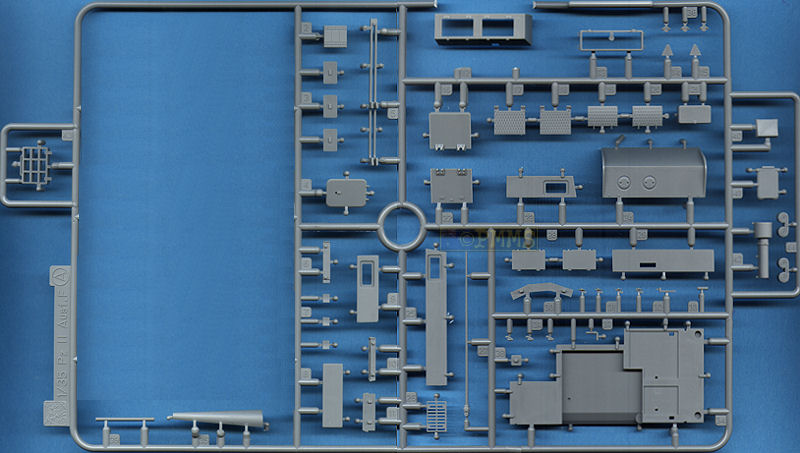
Detail Images

Close new window to return to review
| Panzer Tracts No.2-1 Panzerkampwagen II Ausf.A-C ISBN 0-99815382-2-3  |
Panzers I and II and their Variants: From Reichswehr to Wehrmacht by Walter J. Spielberger ISBN: 0764326240   Covers show original German Language edition and re-issued English Schiffer Publications edition |
| Pz.Kpfw.I/Pz.Kpfw.II
and variants Achtung Panzer No.7 Dainippon Kaiga Co.,Ltd..  |
Thanks to my credit card and the excellent service from ![]() for
the review kit.
for
the review kit.