
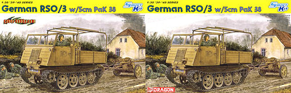
German RSO/3 w/5cm PaK 38
DML 1:35 Scale Smart Kit No. 6684
Kit review by Terry Ashley
It was produced in four main versions;
- RSO/1 with a fully enclosed pressed steel cab and wooden rear cargo bay and was powered by the 3.5L Steyr V8 gasoline engine and transmission as used in the Steyr 1500A 1.5 tonne truck.
- RSO/2 with a simplified slab side metal cab with soft canvas cover and wooden rear cargo bay and was also powered by the 3.5L Steyr V8 gasoline engine and transmission as used in the Steyr 1500A 1.5 tonne truck.
- RSO/3 produced exclusively by KHD had a simplified slab sided metal cab with soft canvas cover and wooden rear cargo bay of the RSO/2 but was powered by the Deutz F4L514 5.3L 4-cylinder air cooled diesel engine. This version is sometimes referred to as the Magirus RSO/3 due to it being produced in the KHD Magirus factory. Photo evidence also shows a fully enclosed cab version of the simplified cab but it’s not known if this was a full production type as well as other cab variations.
- RSO/PaK40 had an lightly armoured low profile steel cab with flat rear bed mounting the 7.5cm PaK40 A/T gun, this was also powered by the 3.5L Steyr V8 gasoline engine.
There were other prototypes developed that had variations with the body and running gear such as a smaller version for mountain troops, a half-track type, amphibian and ambulance versions but none were selected for series production.
The suspension was a very basic design with all steel wheels and just four small leaf springs but the all tracked design and high ground clearance gave it excellent performance in the worst of conditions.
As mentioned the RSO/3 was built exclusively at the KHD Magirus factory and there are some minor detail differences between the RSO/3 cab and externally similar RSO/2 built by other manufacturers and a couple of the decal options are not applicable to the cab type included in this kit, but more on that below.
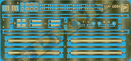
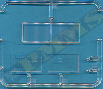
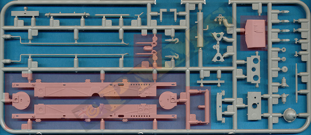
The kit consists of 326 parts in light grey plastic, 144 individual "Magic track" links, 44 etched parts and 5 clear parts plus the decal sheet and the fold out instruction sheet. Dimensionally the kit matches the 1:35 plans in the references listed below within acceptable tolerances.
The standards of moulding are quite high overall but there is the odd bit of fine flash and some of the detail is a little on the heavy side while others are finely done, the fit of some pats and sub-assemblies isn’t up to the usual DML standards especially the drive differentials/axle assembly. The PaK38 parts have quite substantial mould lines and more flash than the RSO parts as might be expected due to the age differences between the two.
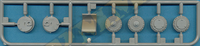
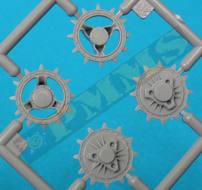
The central round locating lug is a different size between the two with the smaller lug on the idler and larger lug for the drive sprocket. This may seem obvious but if you glue the smaller lug on the drive sprocket the larger lug won’t fit the idler sprocket when you get there, so care is needed.
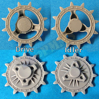
There are new inner ribbed brake drums (parts H3) for this kit but the older parts are still on the sprues so ensure you use the correct H sprue parts, these have a raised section for easy fitting to the sprocket which rectified the fit issue with the first kit parts. The round final drive mountings (parts B15) have three holes for the corresponding pins on the brake drum but one of the holes is smaller than the other two while the pins are all the same size so you may have to open one up slightly.
The central differential/axle assemble has nine parts but the fit is quite sloppy to say least with a fair bit of movement even when there are ‘T’ locating pins and you have to make sure the parts are lined up correctly as it’s very easy to fit these with the wrong orientation.
There are new final drive housings (parts H6, H7) which now include the curved track pin deflectors, these are used to push the track pins back in place as they pass over the sprockets and it’s good to see their inclusion in this kit. Unfortunately the fit is again not that good and you have to ensure they are located perfectly square to the axles as the glue dries, or the drive sprockets will be askew when fitted later. You should also note that the instruction illustrations still show the original parts as well as the new parts which may cause some confusion?
The rear idler units also have the sprocket halves that need careful cleanup of the mould seams and the fit of the parts is again not good with the locating holes being larger than the corresponding pins resulting in quite a bit of movement. You have to be careful fitting the parts E20, E21 and I actually test fitted the axle to the chassis to get the correct angle as the instructions were rather vague. In all the fit of the parts with these two assemblies is not up the DML’s usual standards.
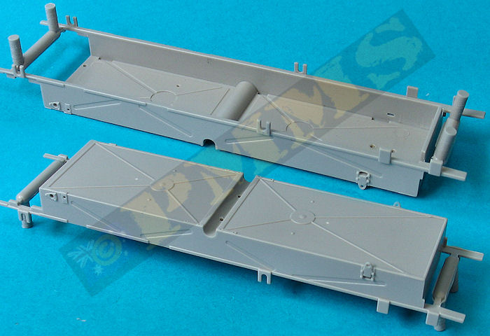
I’ll jump ahead a little here as you have to fit the lower hull front plate (part E13) at the same time as you attach the front idler axle to the hull as the front plate has to actually sit inside the upper section of the hull and simply will not fit if the idler axle is already in place. You will also need to cut off the small front locating tabs on the front panel to allow this to fit into place more easily but in any case you will need to use a little force to get this to click into place inside the hull, in all a rather frustrating exercise.
There is another issue where you have both the drive and idler sprockets with teeth in fitting the track. Both the drive and idler sprockets are meant to be glued in place and when fitting the track the teeth may not align with the track holes, this is not a problem when the sprockets can be rotated to accommodate any alignment issues but not when glued in place and it may be an idea to leave one of the sprockets off until fitting the track to get the alignment right.
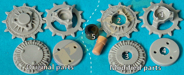
DML have modified the brake drum parts from the previous RSO PaK40 kit requiring a little more work to make the sprockets movable. Firstly "acquire" spare axle stubs and poly caps from any Tamiya kit. 1. Enlarge the hole in the back of the outer sprocket large enough to take the poly cap taking care not to drill though the front of the sprocket hub. 2. drill a hole large enough for the poly cap through the inner sprocket half. 3/4. Drill a hole the size of the axle stub in the brake drum and mounting disc. 5. The end of the poly cap was rounded to fit better into the opening in the outer sprocket in step 1. Care is needed when drilling the holes due to the large size in relation to the sprocket size.
1. The poly is fitted into the assembled drive sprocket and secured when the brake drum is attached, you may need the reduce the height of the ribs on the inside of the brake drum to fit over the poly cap?. 2. Axle stub glued into final drive housing, allow this to dry completely before proceeding.
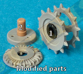
Final drive attached the rear differential assembly, this can be done before or after attaching the differential to the hull.
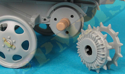
The assembled drive sprocket with poly cap can be added at any time to make fitting the track easier.
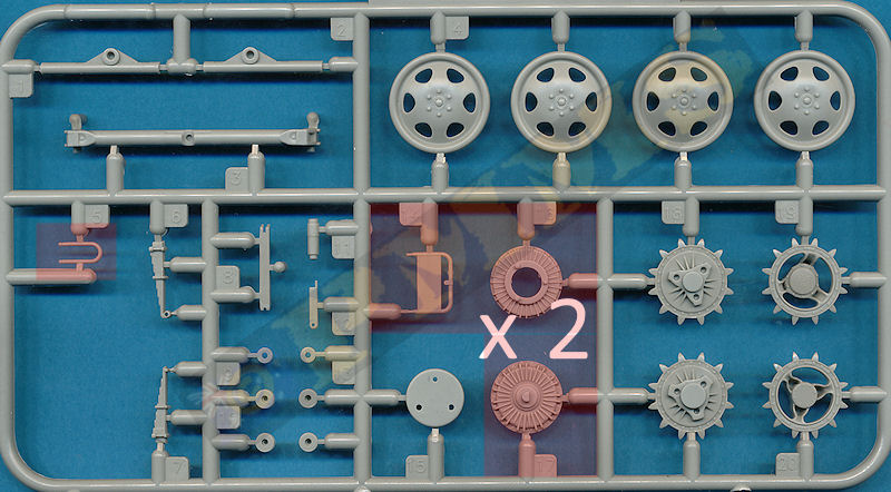
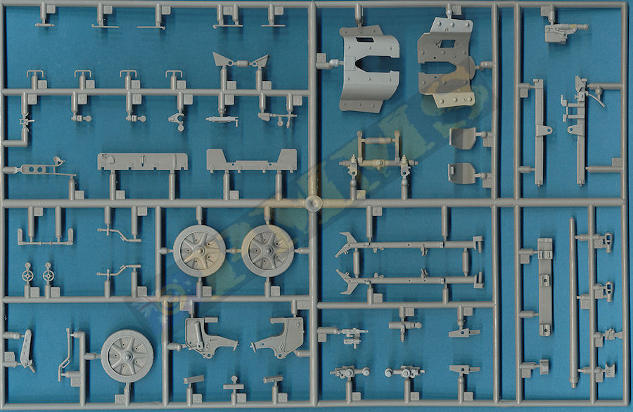
The all steel road wheels have been redesigned with the centre hub rim bolts better depicted although the contour of the wheel dish has a noticeable kink and flat outer face when the actual wheel dish has a curved profile and smoothing out the kink could give a better appearance, this is only a minor point and the wheels do look better with the retooled hub and bolt detail. Of interest is the WWII service manual has illustrations with the kink in the wheel dish as on the kit parts but the available period and museum photos of the RSO don’t show this with the wheel dish having a smooth contour.
The kit also includes small etched strips to add over the road wheel hubs which can be seen on period photos of the RSO/3 and these are easily bent to shape prior to fitting.
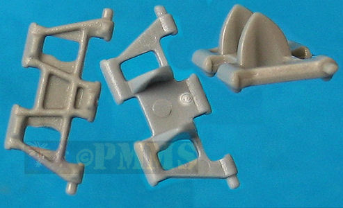
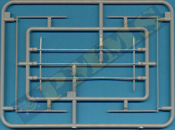
The multi part suspension H frame is nicely moulded with just the mould seams to be removed with the fit of the three main frames (parts A2, B3x2) being very good making for a precise assembly, you just need to ensure the two side frames (parts B3) are parallel with each other. The four road wheel mounting bars parts B1, B2 should be fitted diagonally opposite each other on either side of the frame which isn’t clearly indicated in the instructions. Note you should not glue the four bars in place until you have added the road wheels to ensure all eight wheels touch the ground.
There are small etched discs added to the ends of the road wheel bars for added detail and the road wheels have small mounting plugs glued to the rear hub with the fit to the axle stub also being very good. The assembled suspension frame is later added to the lower chassis with the four leaf springs mating to brackets on the side of the chassis.
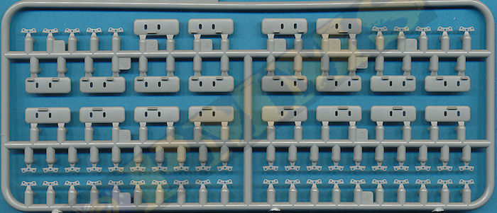
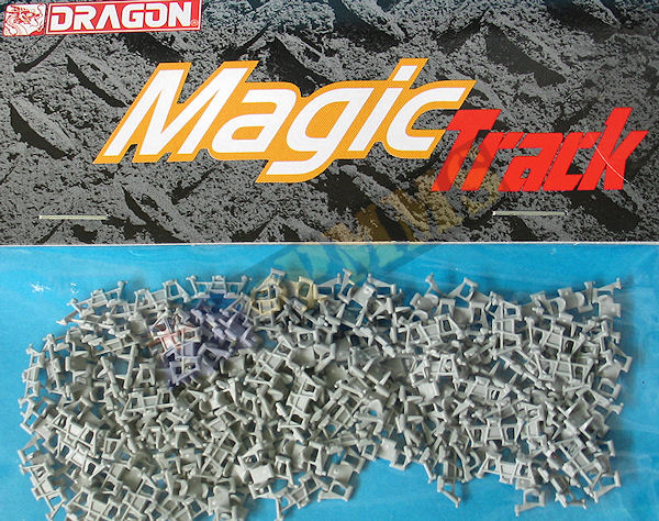
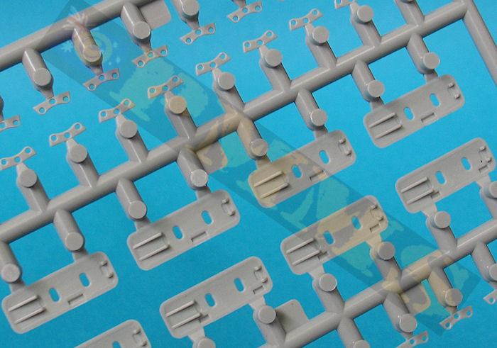
The detail on the link face has a nice cast texture but the pin bolts are not well defined at all with the links fitting together easily and also fit to the sprockets nicely and should look okay once fitted.
The instructions indicate to use 67 links per side but I used 68 links of the review kit, no big deal and when fitting the assembled track runs I needed to move the drive sprocket a little to align the tooth holes correctly as mentioned above.
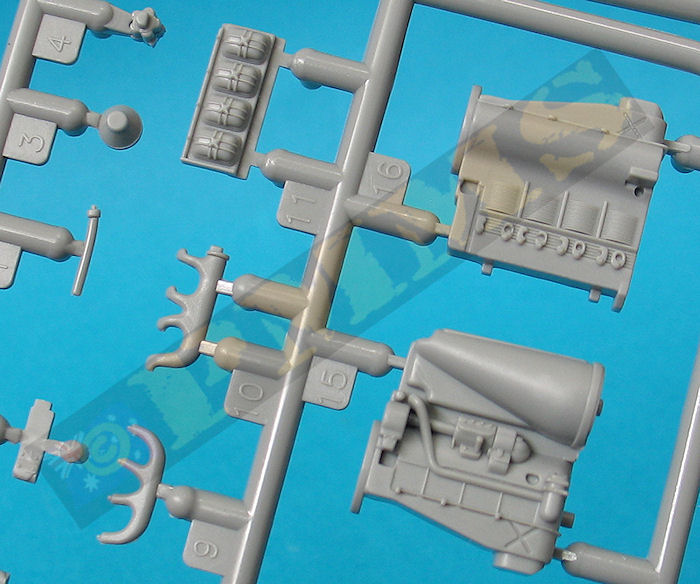
The instructions indicate to fit the two side exhaust pipes (parts A7, A8) but the Deutz diesel engine only has a single exhaust outlet not two as with the Steyr engine so you should NOT fit the right side exhaust pipe (part A8), another issue is the exhaust pipe is designed to fit the Steyr engine and so doesn’t mate with the Deutz engine exhaust, but as you can’t see this after assembly I guess it’s not a real problem?
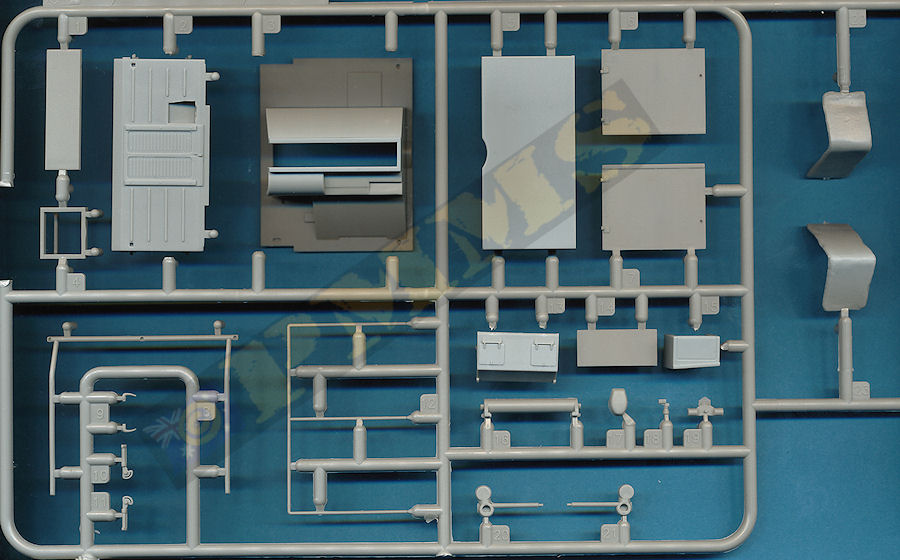
Note you have to fit the exhaust pipe before fitting the inner side bulkheads as it’s very difficult to add this later once the main chassis is assembled. There are additional parts for the inner bulkheads and a large central fuel tank as well as alternate parts for the front and rear crossbar and support frames for the towing pintle, there are alternate parts labelled metal or wooden frames although there is no indication in the instructions which are the appropriate parts to use. It would be more appropriate to the use the “wooden” parts on the new P sprue although they aren’t “wooden” in real life to my knowledge as the exiting A parts have the front crank hole for the Steyr engine and rear mountings for the PaK40 flatbed which makes one wonder why they are offered as an alternative in any case if not just to confuse?
The two front towing hooks (parts A11, A12) should not be fitted to the Magirus factory built vehicles as indicated in the instructions, the locating holes in the chassis frame will also need to be filled. The one piece muffler is added to the rear hull and mated to the left side exhaust pipe; the small exhaust pipe out of the muffler is the wrong shape and should have a rounded profile, not right angled as provided.
Two parts included in the kit but don’t get a mention in the instructions other than just appearing in the step 5 illustrations are the two drive sprocket debris removers (parts A5, A6) attached to the chassis side just in front of the drive sprockets. The holes in ends of the rod could be enlarged for a better appearance but while the debris removers are
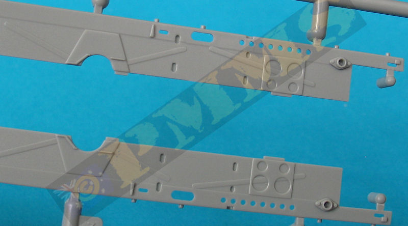
The rear drive sprocket assembly did not fit very well at all, and the two final drive housings were not wide enough to fit over the chassis frames by about 1mm (0.5mm each side). I had to trim some plastic off the side of the chassis to allow the assembly to fit properly.
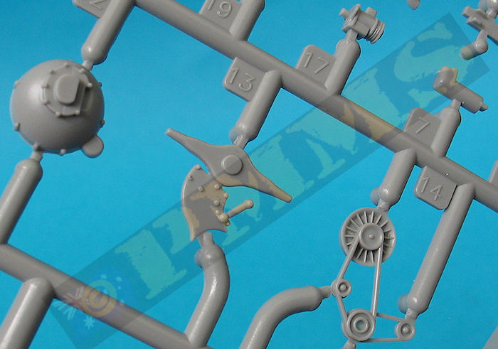
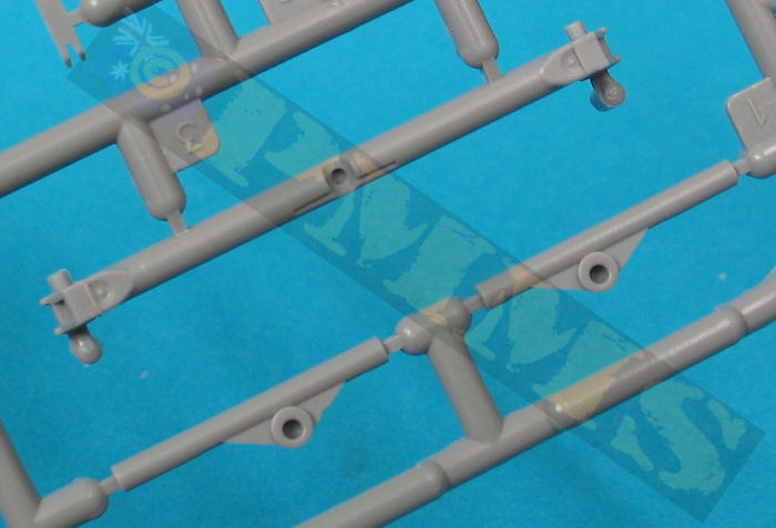
The front pulley assembly includes the large blower fan and smaller pulleys with the belt moulded on and this requires care in handling as the belt is moulded quite thin along with the engine bearers and eight part drive shaft which leads back to the rear axle differential; the shaft and differential are joined later in the assembly.
Added to the rear of the engine is the small drive shaft bracket, the instructions show to use part A14 from the previous PaK40 kit which has to have the triangular mountings cut off either side, but lurking on sprue E is part E19 which is the modified drive shaft bracket all ready to be fitted, so why the instructions show to modify part A14 when you have part E19 ready to go is one of those ponderous questions.
The fully assembled engine in quite impressive with well-defined details and there is plenty wiring and smaller details that could be added if you wanted to display the engine but it’s a pity it’s mostly hidden once the chassis and cab are joined.
Fitting the engine into lower chassis posed a few issues as the tub is designed to take the Steyr engine, firstly you have to omit the inner bulkhead (part D7) as this will simply not allow the engine to fit properly, second there are two rear engine mountings (parts F2, F6) attached to the engine, the right side mounting (part F6) is fitted lower than the left mounting and you will need to shorten (or remove) this to fit inside the tub. Thirdly the front engine bearer (part F13) will need the ends cut off as these will foul on the Steyr engine mountings moulded into the tub side panels and lastly the exhaust pipe simply doesn’t mate with the engine manifold pipe outlet by a long way as again the side exhaust pipe is designed for the Steyr engine, not the Deutz diesel.
But I guess as none of the engine and its fit issues can be seen after assembly you can simply leave the engine out and all of the above becomes academic in any case.
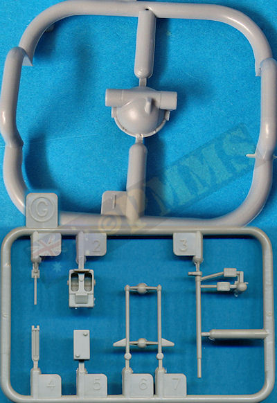
The floor panel has separate driver’s foot pedals and steering box with separate steering levers but these are way too short by about 4mm and the should also have a bend backwards at the top of each lever as they are not straight as in other RSO versions, replacing these with longer plastic rod would be advisable. There is also no instrument panel or dials included, this should be a strip along the top cab line with a small cluster on the left hand side, the gear lever next to the driver’s seat is also missing and should be added.
The seats have the lower mounting frames/box with canvas seats; the right hand passenger seat has to be reduced in width by about a 1mm (trim the inner edge) to fit into the cab as the engine compartment is offset from the centreline. The separate top engine compartment hatch opening is quite thin and if left open is the only way the engine can be seen after assembly. The clear one piece windscreen has two small side attachments but is missing the two wiper blades and inner wiper motors which you may want to add from scratch?
The separate doors have small outside door handles added along with separate clear ‘glass’ sections and you can position the doors open or closed as you wish, unfortunately there is no inner door detail included and there should be an inner frame forming a large storage compartment on the bottom half of the door panel for the windows when not in use as well as the inside door handle box with handle as well as grab handle on the forward edge. If you plan to show the doors open adding all this missing detail would be a good option as they are rather plain as they come.
It is advisable to temporarily (or permanently as you wish) fit the doors in place as you attach the cab front panel to ensure the cab front, rear wall and the doors all align correctly as it’s easy to get a poor door fit if you glue the rear wall and front cab section in place and then try and fit the doors.
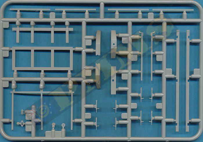
The kit provides alternate wood or metal roof frames (in plastic obviously) to use as required but no actual roof canvas provided and there is scope to add extra details in the cab area if you are leaving the door open to improve the appearance.
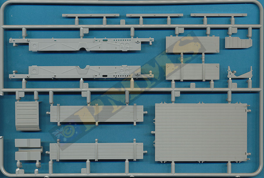
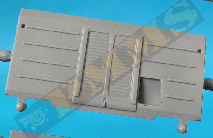
On the real panel is the early style single tail light but given the period these vehicles were produced the later convoy light would seem more appropriate but you would have to scavenge one to use? The three side panels can be attached in the raised or lowered as required?
There are two styles of fine plastic and etched securing clips provided that need bending to shape but again no indication which is the better option, period photos show both types used but the longer clips seem more common on the RSO2/3. If using the longer clips you need to cut off the raised detail for the etched short clip fittings and also the locating holes for the shorter clips will need to be filled on the side panels.
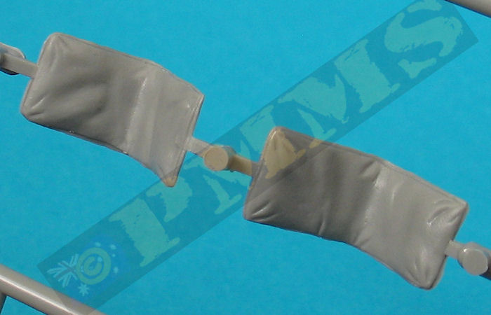
Included in the kit are 20 wide snow shoes that can be attached to the tracks or stowed in the cargo bay behind the front panel or attached to etched mountings on the folding side panels and again there is tilt frames for the cargo bay but no actual canvas cover which can be made from tissue or similar if you wish or wait for the inevitable resin covers to be produced?
The gun assembly is fairly straightforward but some of the parts need extra cleanup for a proper fit and there are some joins to be attended too such as on the two part gun cradle. The two spaced shields are a little on the heavy side with the trails able to be positioned in the firing or travel configuration.
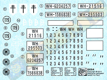
Note a couple of the decal options are for RSO/2s and not /3s with option two also of a vehicle with a different style cab than that included in the kit making this option not applicable to this kit, it is one of the more commonly photographed RSOs in publications and clearly shows the different cab features.
Option 6 is of a museum preserved RSO so the cam scheme and marking may not be authentic, so take care is selecting this option.
| Option 1:
Unidentified Volksgrenadier Division, Eastern Front, 1944 Option 3: Free French Army, France, 1944 (note, this vehicle is an RSO/2 as mentioned above)  Option 5: 21.Pz.Div. Western Front, 1944   |
Option 2:
Unidentified Unit, Eastern Front, 1944 Option 4: 21.Pz.Div. Normandy, 1944  Option 6: Unidentified Unit, Western Front 1944/5 (note, this is museum preserved vehicle as mentioned above)  |
There are some areas that need care during assembly as the fit is not that good and some areas that could do with additional detailing such as the cab interior while the rear cargo bay has alternate latches and the nice bonus of the large snow shoes for the tracks although you only get the tilt frames and no actual canvas cover for the cab or cargo bay. Including the full covers rather than the aging PaK38 may have been a better option as the PaK38 wasn’t a “standard” addition to the RSO.
But overall it is a nice kit that looks very much the part if none if the issues mentioned above are of concern and with a little work will build into an excellent kit of the simplified cab version of the RSO/3.
Rating 8/10
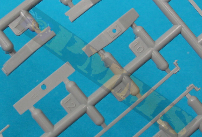
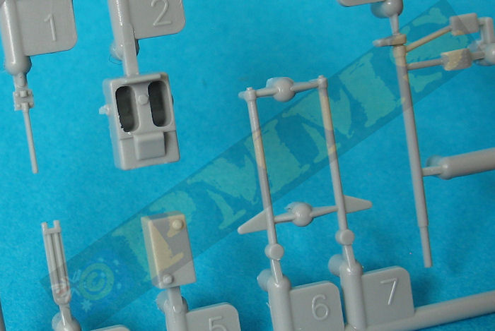
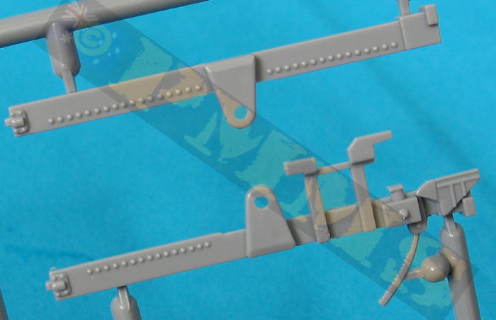
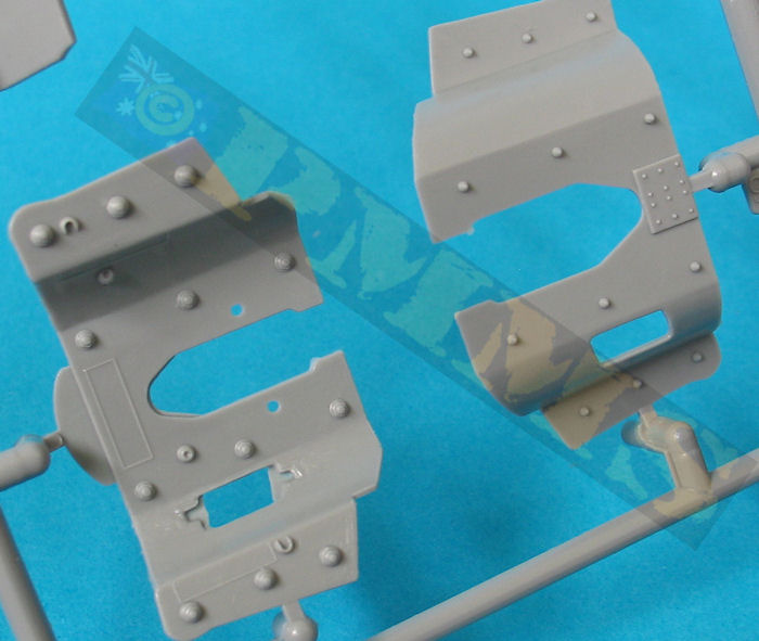
Sprue images
Click on thumbnails for larger view

Build images
Sprue detail images


| Raupenschlepper Ost - RSO Nuts & Bolts Vol.29 176 pages, Soft Cover  |
7.5cm Pak 40/4 auf gep. Selbstfahrlafftte Raupenachleper OST (RSO) Nuts & Bolts Vol. 09 Revised  |
| Raupenschlepper Ost (RSO) Militar's Kits Special Volume 2 ISBN 2-9509986-2-3  |
Allied & Axis No.20 Raupenachleper OST Ampersand Publishing  |
