
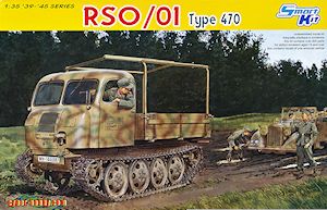
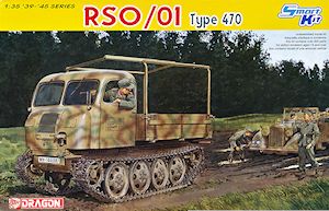
RSO/01 Type 470
DML 1:35 Scale Smart Kit No. 6691
Kit review by Terry Ashley
It was produced in four main versions;
- RSO/1 with a fully enclosed pressed steel cab and wooden rear cargo bay and was powered by the 3.5L Steyr V8 gasoline engine and transmission as used in the Steyr 1500A 1.5 tonne truck.
- RSO/2 with a simplified slab side metal cab with soft canvas cover and wooden rear cargo bay and was also powered by the 3.5L Steyr V8 gasoline engine and transmission as used in the Steyr 1500A 1.5 tonne truck.
- RSO/3 produced exclusively by KHD had a simplified slab sided metal cab with soft canvas cover and wooden rear cargo bay of the RSO/02 but was powered by the Deutz F4L514 5.3L 4-cylinder air cooled diesel engine. This version is sometimes referred to as the Magirus RSO/03 due to it being produced in the KHD Magirus factory. Photo evidence also shows a fully enclosed cab version of the simplified cab but it’s not known if this was a full production type as well as other cab variations.
- RSO/PaK40 had an lightly armoured low profile steel cab with flat rear bed mounting the 7.5cm PaK40 A/T gun, this was also powered by the 3.5L Steyr V8 gasoline engine.
There were other prototypes developed that had variations with the body and running gear such as a smaller version for mountain troops, a half-track type, amphibian and ambulance versions but none were selected for series production.
The suspension was a very basic design with all steel wheels and just four small leaf springs but the all tracked design and high ground clearance gave it excellent performance in the worst of conditions.
The kit consists of:
- 326 parts in light grey plastic (97 shown as not used)
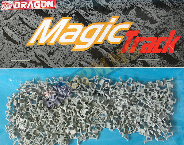
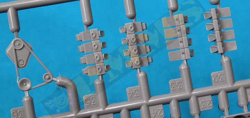
- 144 individual "Magic track" links
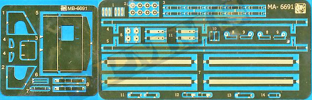
- 61 etched parts
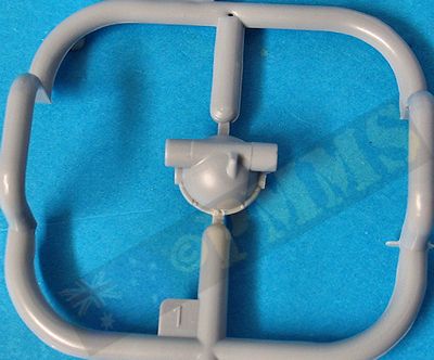
- 7 clear plastic parts
- 1 decal sheet
- 1 fold out instruction sheet.
Dimensionally the main kit parts match the 1:35 plans in the references listed below within acceptable tolerances and the standards of moulding is quite high overall with virtually no flash and just the usual mould seam lines and many plastic nodes to be removed. Care is needed during sprue clean-up on some parts as the attachment point overlaps the detail, most notably on the inside of the door frames while on other the attachment is raised from the part making clean-up easy.
The detail is very finely done overall with the most concern being with the suspension where the fit will require more care especially with the drive differentials/axle assembly. But overall the fit is good and the various sub-assemblies allow you to work on one while the glue on other dries, the one area that needs most care as with many DML kits is the instructions that are a little confusing in parts and you need to carefully study these before gluing or cutting to avoid any problems.
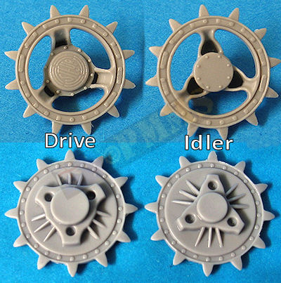
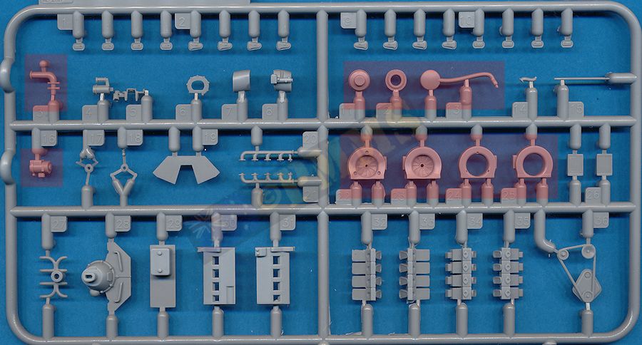
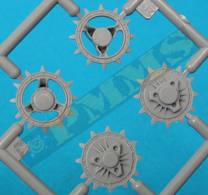
On the sprockets the central round locating lug is a different size between the two with the smaller lug on the idler and larger lug for the drive sprocket. This may seem obvious but if you glue the smaller lug on the drive sprocket the larger lug won’t fit the idler sprocket when you get there, so care is needed.
Due to the suspension being from the first RSO/Pak 40 kit the fit issue between the brake drum (part B16) and final drive (part B21) resurfaces as there are no actual locating pins on the drum or sprocket and you have to ensure it is positioned evenly on the sprocket. Another minor point to watch is the sprocket part B21 isn’t actually numbered on the sprue for some reason but as all the others are numbered you can find B21 by process of elimination. The round final drive mountings (parts B15) have three holes for the corresponding pins on the brake drum but one of the holes is smaller than the other two while the pins are all the same size so you may have to open one up slightly. The central differential/axle assemble has nine parts but the fit is not the best with a fair bit of movement even when there are ‘T’ locating pins and you have to make sure the parts are lined up correctly as it’s very easy to fit these with the wrong orientation.
There is a retrograde step with this kit as it uses the final drive housings (parts A16, A17) from the first RSO PaK 40 (kit #6640) and therefore these don’t include the curved track pin deflectors that were on the revised final drives from the RSO/03 w/5cm PaK 38 kit. These deflectors are used to push the track pins back in place as they pass over the sprockets and you will need to add this detail yourself to replicate the final drives correctly. It is quite disappointing that the small H sprue from the RSO/03 kit couldn’t be included for the revised final drives yet we have the full sprue E from the RSO/03 kit included just of the 2 part Notek light with all other E parts being redundant, well almost as we’ll see below.
The fit of the final drives is not that good and you have to ensure they are located perfectly square to the axles as the glue dries, or the drive sprockets will be askew when fitted later. When fitting the suspension frame to the hull you may need to enlarge the holes in the spring (part B6) to allow the pins on the securing bracket (parts A25) to fit properly, also the holes in the forward hull bracket will also need to be enlarged to allow the proper fitting of the pin on the spring retaining bracket (parts A26).
The rear idler units also have the sprocket halves that need careful clean-up of the mould seams and the fit of the parts is again not good with the locating holes being larger than the corresponding pins resulting in quite a bit of movement. You have to be careful fitting the parts E20,E21 and I actually test fitted the axle to the chassis to get the correct angle as the instructions were rather vague. In all the fit of the parts with these two assemblies is not up the DML’s usual standards.
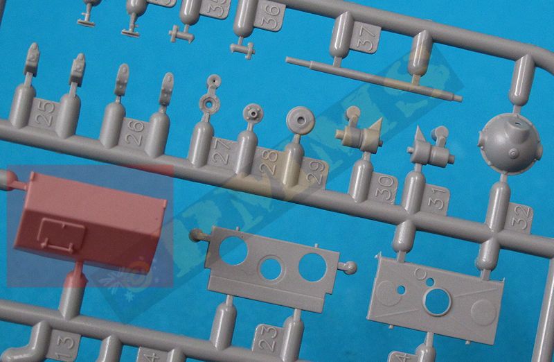
I’ll jump ahead a little here to the fitting of the lower hull front plate which is supplied as etched parts (parts MB5, MB1/2) with this kit. The original plastic part E13 is till included if you prefer to use plastic although the etched parts are fairly straightforward to assemble as far as etched parts go.
The instructions indicate to use the idler axle (part A20) and idler mountings (parts A9,A10) but these parts will prevent the etched front panel from fitting and you should actually use the revised idler axle on sprue E (part E16) and the idler mountings (parts E20,E21), these parts set the axle closer to the hull and allow the front panel to fit correctly.
Note, the end plate assemblies need to be fitted at the same time as you attach the front idler axle to the hull as the front plate has to actually sit inside the upper section of the hull and will not fit if the idler axle is already in place. You will also need to cut off the small front locating lugs inside the front hull to allow the plastic panel to fit if you decide to use this instead of the etched panel.
There is another possible issue where you have both the drive and idler sprockets with teeth in fitting the track. Both the drive and idler sprockets are meant to be glued in place and when fitting the track the teeth may not align with the track holes, this is not a problem when the sprockets can be rotated to accommodate any alignment issues but not when glued in place and it may be an idea to leave one of the sprockets off until fitting the track to get the alignment right.
DML have modified the brake drum parts from the previous RSO PaK40 kit requiring a little more work to make the sprockets movable. Firstly "acquire" spare axle stubs and poly caps from any Tamiya kit. 1. Enlarge the hole in the back of the outer sprocket large enough to take the poly cap taking care not to drill though the front of the sprocket hub. 2. drill a hole large enough for the poly cap through the inner sprocket half. 3/4. Drill a hole the size of the axle stub in the brake drum and mounting disc. 5. The end of the poly cap was rounded to fit better into the opening in the outer sprocket in step 1. Care is needed when drilling the holes due to the large size in relation to the sprocket size.
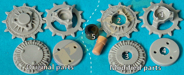
1. The poly is fitted into the assembled drive sprocket and secured when the brake drum is attached, you may need the reduce the height of the ribs on the inside of the brake drum to fit over the poly cap?. 2. Axle stub glued into final drive housing, allow this to dry completely before proceeding.
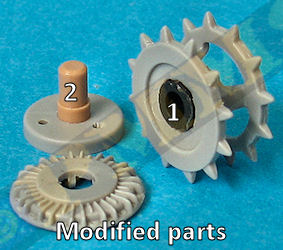
Final drive attached the rear differential assembly, this can be done before or after attaching the differential to the hull.
The assembled drive sprocket with poly cap can be added at any time to make fitting the track easier.
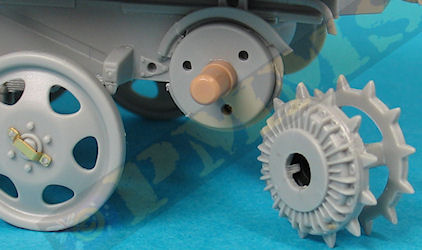
The all steel road wheels from the RSO/03 kit have the centre hub rim bolts better depicted although the contour of the wheel dish has a noticeable kink and flat outer face when the actual wheel dish has a curved profile and smoothing out the kink could give a better appearance. The kit also includes small etched strips to add over the road wheel hubs which can be seen on some period photos of the RSO but are not at all common so is probably best to leave these strips off the wheels unless you have specific reference showing their use.
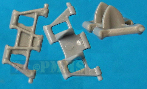
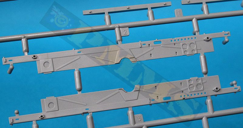
The multi part suspension H frame is nicely moulded with just the mould seams to be removed with the fit of the three main frames (parts A2, B3x2) being very good making for a precise assembly, you just need to ensure the two side frames (parts B3) are parallel with each other. The four road wheel mounting bars parts B1, B2 should be fitted diagonally opposite each other on either side of the frame which isn’t clearly indicated in the instructions. Note you should not glue the four bars in place until you have added the road wheels to ensure all eight wheels touch the ground.
There are small etched discs added to the ends of the road wheel bars for added detail and the road wheels have small mounting plugs glued to the rear hub with the fit to the axle stub also being very good. The assembled suspension frame is later added to the lower chassis with the four leaf springs mating to brackets on the side of the chassis.
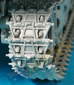
The instructions indicate to use 67 links per side but I used 68 links of the review kit, no big deal and when fitting the assembled track runs I needed to move the drive sprocket a little to align the tooth holes correctly as mentioned above.
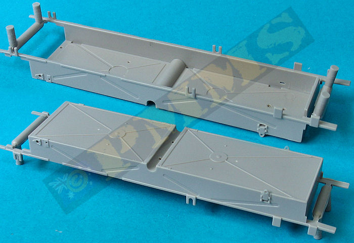
Note you have to fit the exhaust pipes before fitting the inner side bulkheads as it’s very difficult to add this later once the main chassis is assembled. There are additional parts for the inner bulkheads and a large central fuel tank as well as the front and rear crossbar and support frames for the towing pintle.
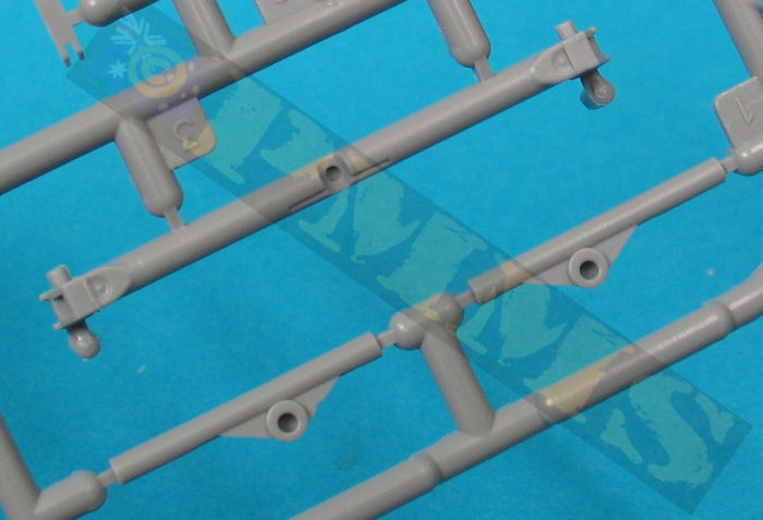
The front hooks (parts A11, A12) are too long and should be shortened by about 1.5mm with the one piece muffler added to the rear hull and mated to the side exhaust pipes, the small exhaust pipe out of the muffler has the correct rounded profile along with small etched parts. Note you shouldn’t attach the top cross member (part A19) until after the engine has been added later. 
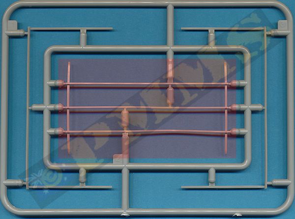
The two drive sprocket debris removers (parts A5, A6) are attached to the chassis side just in front of the drive sprockets and the holes in ends of the rod could be enlarged for a better appearance.
The rear drive sprocket assembly did not fit very well at all, and the two final drive housings were not wide enough to fit over the chassis frames by about 1mm (0.5mm each side). I had to trim some plastic off the side of the chassis to allow the assembly to fit properly.
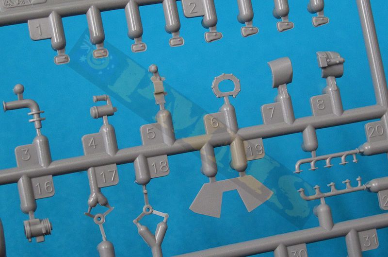
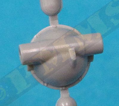
The large distinctive top mounted cooler blowers have well defined fan blades with separate small ‘star’ brackets plus separate square oil coolers with subtle mesh texture and look quite impressive. Take note that the lip around the top of the fan units should be there so don’t trim this thinking it might be excessive flash.
Other parts include the alternator, distributor and the front pulley assembly with the belt moulded on and this requires care in handling as the belt is moulded quite thin. Note that the two cooler blowers just sit on the edge of the two engine end plates (parts E19, E28) so check the cooler blowers sit level before the glue dries. The alternator mounting (part E5) is included but for some reason the alternator (part E16) doesn’t get a mention in the instructions and this can be fitted to the mounting and aligned with the fan belt pulley. The two exhaust manifolds are located under the cylinder banks either side of the engine block without any problems, just note these are different either side but it’s not a big deal if fitted to the opposite side as the difference is the angle of the gaskets at the base of the pipes which you can’t see when the engine if fitted to the chassis.
The rear transmission housing in three parts is joined to the engine mounting bracket, unfortunately this is fractionally too wide to fit between the hull tub sides and the small locating pins either side had to be removed and the ends of the bracket trimmed slightly to fit into the tub. These locating pins are not really needed as there are additional locating pins on the bottom of the sump that fit into holes in the tub floor which are sufficient to locate the engine correctly.
There is an eight part drive shaft which leads back to the rear axle differential; the shaft and differential are joined later in the assembly. The new air cleaner parts fit to the top of the engine and not inside the cab as with the first RSO kit and makes assembly and fitting of the body a far easier task.
The fully assembled engine in quite impressive with well-defined details and there is plenty wiring and smaller details that could be added if you wanted to display the engine but it’s a pity it’s mostly hidden once the chassis and cab are joined. You can actually see the front of the engine through the radiator grills if the grill cover isn’t fitted as is the case with the real vehicle.
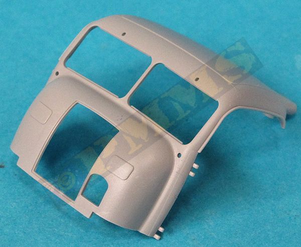
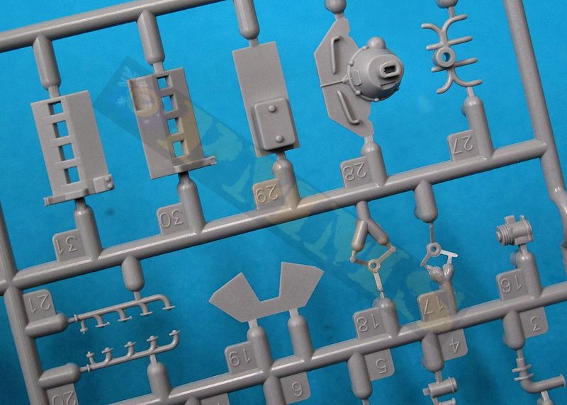
Important to note is the instructions show to fit the Notek light recess part H3 from the outside of the cab but this has to fitted from the inside before any other assembly, this will become obvious but if you have assembled the rest of the cab before adding the light assembly you will have a problem. The Notek light itself is in three parts, the light, mounting post and small round base plate and its best to glue these parts together before fitting into the cab recess to make things easier.
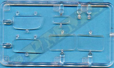
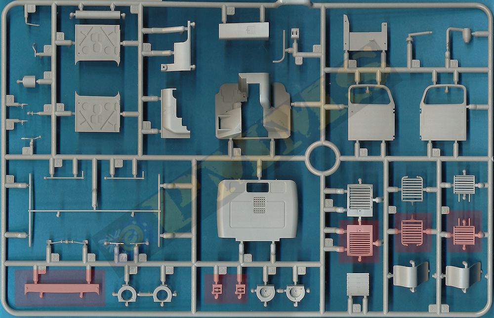
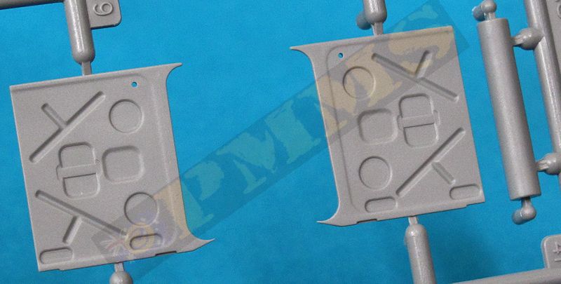
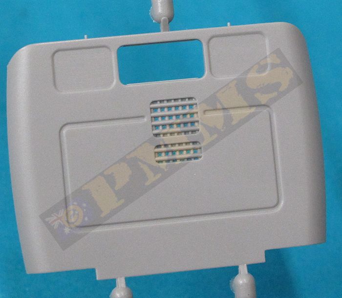
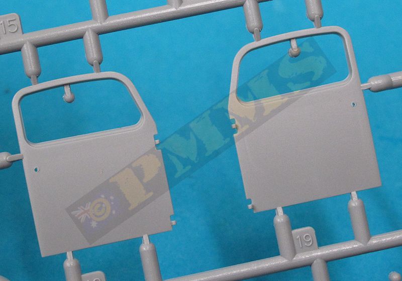
The rear cab wall is a separate part with small intake grills and you may want to replace the oversized mesh with fine brass screen for a better appearance, the rear window is also added and the wall glued to the roof. Temporally fitting the doors will make sure you fit the wall at the correct angle but don’t glue the doors at this stage. The doors themselves have separate inside panels that have nice recessed detail and separate outer door handles but despite the inner locating hole there are no door or window winder handles for the inside of the doors. The clear glass windows are moulded clear but extremely thick so you can only fit these as they come in the raised position and they do give the correct “slant” of the window glass when fitted for a good appearance.
The two separate front windscreen clear sections need extreme care when removing form the sprues as there is a recess top and bottom of the clear parts that fit over small raised tabs inside the cab window openings. Unfortunately the sprue attachments on the windows are right over the recesses and you will need to carefully trim the excess plastic out of the recesses for the windows to fit properly but due to the hard clear plastic this is not easy to do without leaving a blemish visible on the clear windows, so take care. Also included with the kit are self-adhesive window masks for all the windows to aid with the painting
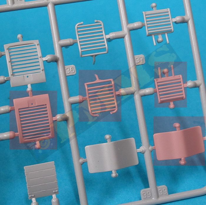
You also get separate windscreen wipers and small lights to add to the cab as well as alternate radiator grills, one with open grill louvers and the other with the cold weather cover, this is a little on the thick side when compared to period photos and thinning the cover could improve the appearance. The instructions indicate to use the grill and cover (parts H33, H35) as the other grill (part H34) appears to have louvers used on the diesel engine RSO.
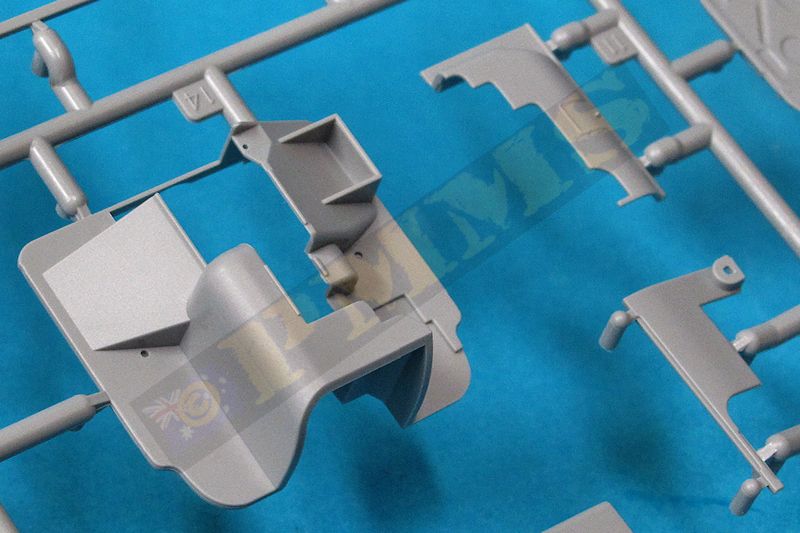
On the inside you get the floor with partial engine cover with separate engine side and top covers added, these have moulded on mesh panels that again could be replaced with etched mesh for a better appearance There is also the side mounted gear shift lever, two floor mounted gear levers, driver’s foot pedals and steering levers added to the small floor junction box which in turn is attached to the floor, there is also the fuel tank filler pipe on the right side and all parts fitted without any problems. Items not present include the instrument panel which should be located lengthwise under the windscreen on the left side with an open glove compartment on the right side as well as the wiper motors adjacent to the outside wipers plus some wiring inside the front cab wall if you wish to add this.
The crew seats have two part frames with the springs moulded solid but as you can’t see these after assembly it’s not a big deal they have no spring texture. The canvas seat cover is sat on top of the frame to complete the seats which are then fitted to the floor locating hole while resting against the engine cover, the fit here is not that precise and fitting the seats with the backrest level with the rear of the floor section is the desired position.
One really strange thing with the kit is the instructions show to only fit the driver’s seat with the co-driver’s seat listed among the parts not used and is not shown in the instructions diagrams. I have no idea why this is the case as you should fit both the driver’s and co-driver’s seats which is the normal arrangement for the RSO/01. The locating hole for the co-driver’s seat is there in the floor pan so again it’s a real mystery why the seat is not shown fitted, but as said just fit it anyway which ends of problem.
The fit of the body to the lower floor is a little vague as there isn’t any actual locating lugs inside the cab and you must ensure the floor is glued level with the bottom edge of the cab, the floor can easily slide up into the cab if not careful so make sure all four corners remain level as the glue dries. Also fitting the doors required a little trimming, the raised detail on the inner edge of the top hinge needed to be removed and the top of the window sill shaved down slightly to allow for the best fit but test fitting the doors will determine if any trimming is needed on your kit.
There is a cab mounting plate (part H15) and this is best glued to the bottom of the cab and not to the hull as indicated as this made it easier to fit the cab which is a good fit either way so this is up to the individual really.
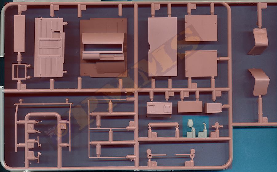
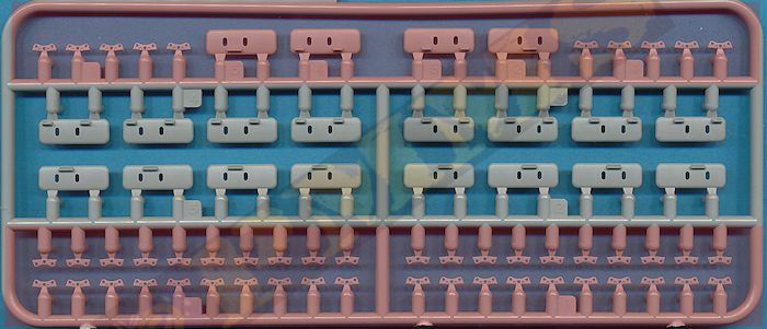
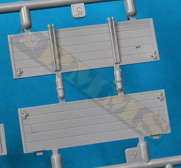
There are two styles of fine plastic latches included (parts B23, B24) but no indication which is the better option, period photos show both types used so the choice is optional and best to refer to references for the applicable vehicle if available. The small etched securing clip brackets provided need bending to shape before fitting which shouldn’t be a problem but they don’t fit into the recesses provided on the panels and you will need to enlarge the recess for the brackets to fit correctly.
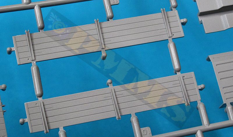
There are additional side strips in both plastic and etched brass to be added depending if you are fitting the snow show stowage or but there should also be another strip to use for the standard cargo bay that isn’t included as well as six tie down cleats along to top edge for securing the tarp cover if fitted and these also can be added for additional detail.
Included in the kit are 20 wide snow shoes that can be attached to the tracks or stowed in the cargo bay behind the front panel or attached to etched mountings on the folding side panels and again there is tilt frames for the cargo bay but no actual canvas cover which can be made from tissue or similar if you wish or wait for the inevitable resin covers to be produced?
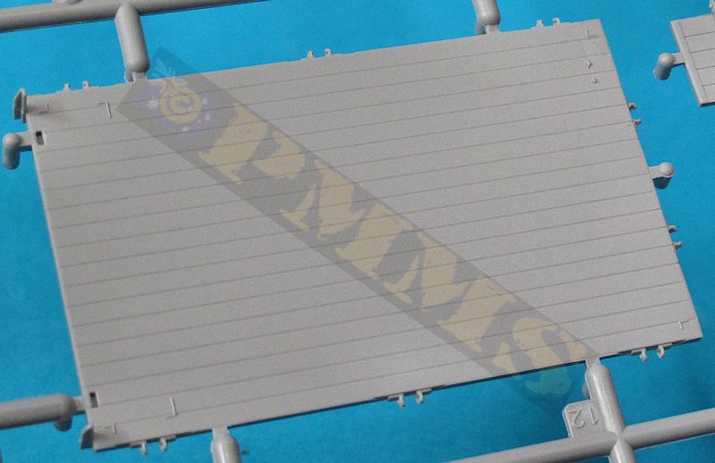
The Assembled rear tray with its three underside cross beams fits precisely to the lower hull by way of the locating pins for a quick and easy final assembly.
The paint schemes list show a good cross section of finshes but you could really paint the kit in any scheme as it was widely used during the later war period on both the Eastern and Western fronts..
The instructions as mentioned are typical DML I’m sorry to say with an array of miss numbered parts, parts not identified and unexplained options which causes confusion. This has been commented on forever about DML instructions yet they don’t seem to improve?| Option 1:
Unidentified Unit, Eastern Front, 1944 Option 3: Unidentified Unit, 1942  Option 5: Unidentified Unit, Eastern Front, 1943  Option 5: Unidentified Unit, Eastern Front, 1943  |
Option 2:
Ski.Jg.Div, Eastern Front, 1944 Option 4: Volksgrenadier Div,Western Front 1944/5  Option 6: Unidentified Unit, Eastern Front, 1943  |
The kit will build into an excellent replica of the RSO/01 and is clearly the best kit of the type available today but there are numerous areas that can do with additional details and refinement such as the road wheel contours the cab interior and exterior details as outlined above. There are some areas that need care during assembly as the fit is not that good as others while the rear cargo bay has alternate latches and the nice bonus of the large snow shoes for the tracks although you only get the tilt frames and no actual canvas cover cargo bay.
The instructions again have some strange steps such as not including the co-driver’s seat and using the wrong front idler axle parts but overall it is a nice kit that looks very much the part if none if the issues mentioned above are of concern and with a little work will build into an excellent kit of the steel cab RSO/01.
Rating 8/10
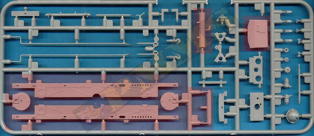
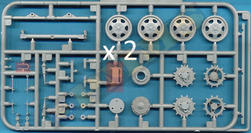
Sprue images
Click on thumbnails for larger view

Sprue detail images

Close new window to return to page
| Raupenschlepper Ost - RSO Nuts & Bolts Vol.29 176 pages, Soft Cover  |
Raupenschlepper Ost (RSO) Militar's Kits Special Volume 2 ISBN 2-9509986-2-3  |
| Allied & Axis No.20 Raupenachleper OST Ampersand Publishing  |
Ground Power Magazine #119- 4/2004 Published by GALILEO Publishing Co.,Ltd  |
