
German sWS with 3.7cm FlaK43
Anti-Aircraft Gun
Great Wall Hobby 1:35 kit #L3521
Review by Terry Ashley
The sWS was powered by a 6 cylinder, water-cooled Maybach HL42TRKMS gasoline engine generating 100 horsepower (75 kW) which gave it a top speed of 27 klm per hour (17.0 mph) on good roads with a load capacity of 4,000 kilograms (8,800 lb).
This version, like the sWS with 2cm Flakvieling (kit #L3525) were not official production types but field modifications with this version and the cam scheme clearly shown in a well know photo along with the production sWS armoured cab 3.7cm FlaK43 version (kit #L3516) of the same unit.
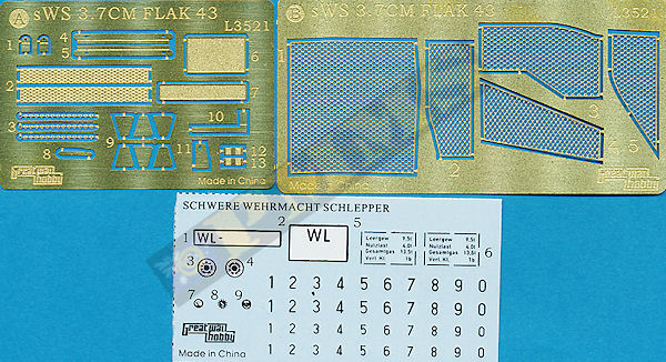
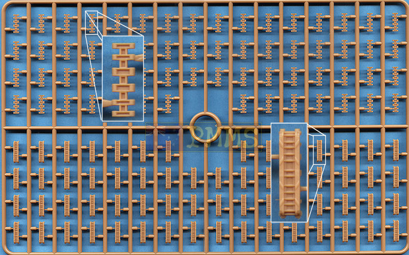
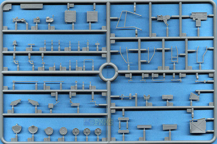
The kit has 337 parts in both light beige and light gray plastic with another 248 individual track links in the beige plastic plus 4 clear and 27 etched parts on 14 sprues and one metal fret. Added to this are the decal sheet and 10 page instruction booklet and a colour poster of the box art included which also has the colour painting guide on the back.
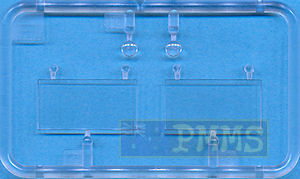
Clear parts
The quality of the moulding is excellent with clean crisp details virtually free of any flash or pin marks and any present is quite minor and easily dealt with. There are the usual mould seam lines to be removed and as some of the parts are extremely small and you will need to take care removing these from the sprues and during assembly.
Dimensionally the kit measures up very well against the 1:35 plans in the Tank Magazine and Panzer Tracts books listed below with parts such as the running gear, track and hull widths being spot on. There is also disagreement on some dimensions between the plans with the kit matching parts of one plan but not on the other plans and visa-versa. So overall things sort of even out and the kit doesn’t look out of proportion when compared the available photos.
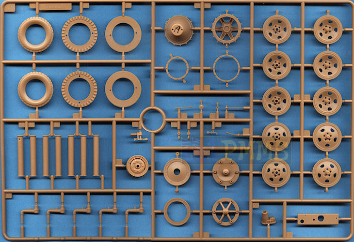
Included in the kit are a number of options including two styles of front wheel rims, the initial large and later smaller diameter drive sprocket as well the initial spoke idler and the solid disc idler plus a full set of full dish road wheels.
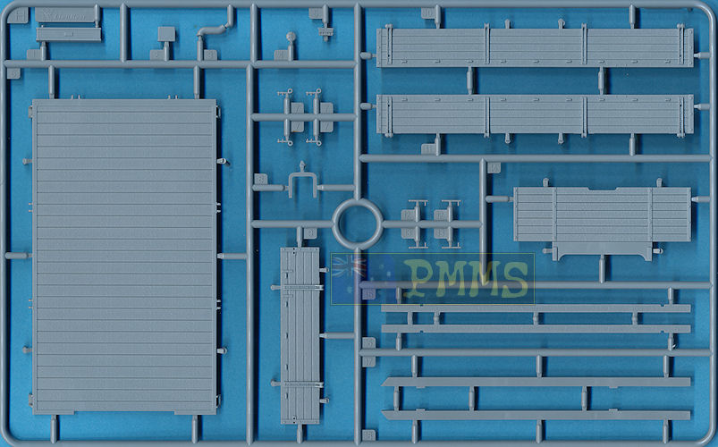
The kit is also broken down into sub-assemblies which can be built separately and brought together at final assembly which allows you to work on one while the glue/paint dries on another and this helps speed up assembly. The sub-assemblies are the lower chassis/suspension, forward cab/engine compartment and rear cargo tray, plus of course the 3.7cm FlaK 43.
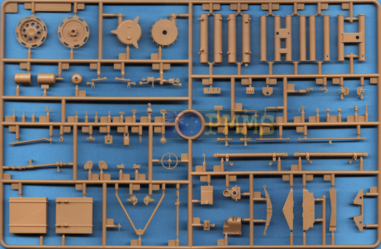
These channels fit neatly inside the chassis without any problems and there is also a detailed 5 part winch, 4 part fuel tank, a couple of bulkheads and two air tanks added inside the chassis as well as a 5 part winch cable guide. This guide has three very small roller wheels trapped between the two sides and removing these rollers from the sprue and fitting will really test you patience as well as eyesight. Considering some of these chassis parts can't be seen after the rear cargo bay is fitted you could probably save yourself a bit of work by not fitting some of the parts, it’s your choice.
Added to the chassis side are the 5 axles per side which have subtle cast texturing on the arms and you have to be careful removing the moulding seams so not to eliminate the texturing, the arms are hidden by the road wheels anyway so it probable doesn’t matter a lot?
The axle arms have a small pin to ensure they are all aligned correctly in the neutral position and if you wanted to articulate the suspension you just cut off the pin and reposition the arm and at the back the idler axle mounting has a separate threaded adjustment bolt that fits through the hull bracket with a separate tensioning bolt and gives very good definition to the mounting.
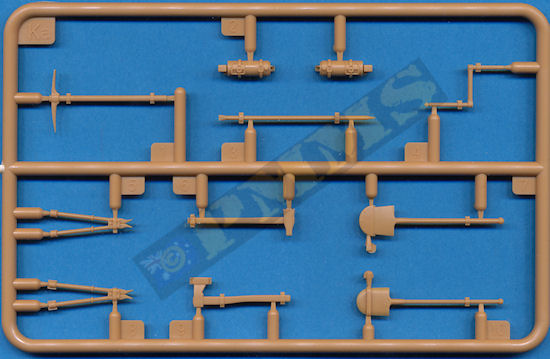
There is also a three part towing pintle, boarding step and compressed air valve as well as the towing pintle on the front of the chassis with separate pin.
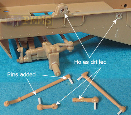
There are 4 steering linkages added to the left side of the chassis and as we have seen on some other kits these are not designed to be movable and once glued in place negate the workable steering?
This does allow you to position the front wheels at any angle as you glue the linkages for a bit of animation and it’s also a simple task to modify the steering linkages to make these workable for truly workable suspension if you wish.
This entails cutting the locating pins from the parts to fill the corresponding locating holes and when dry drill holes for the thin plastic rod pins (I used 0.6mm plastic rod) added to the appropriate places on the linkages. You then slip the pins through the holes and secure by heat melting the ends of the pins which results in fully workable steering.
This entails cutting the locating pins from the parts to fill the corresponding locating holes and when dry drill holes for the thin plastic rod pins (I used 0.6mm plastic rod) added to the appropriate places on the linkages. You then slip the pins through the holes and secure by heat melting the ends of the pins which results in fully workable steering. See images.
Holes drilled in chassis and linkages to take the pins added to the rods.
The pins are heat welded to secure in place.
Note; the locating pins are cut from the parts and glued into the locating holes before
drilling the pin holes.
Modified steering linkages allow for full movement.
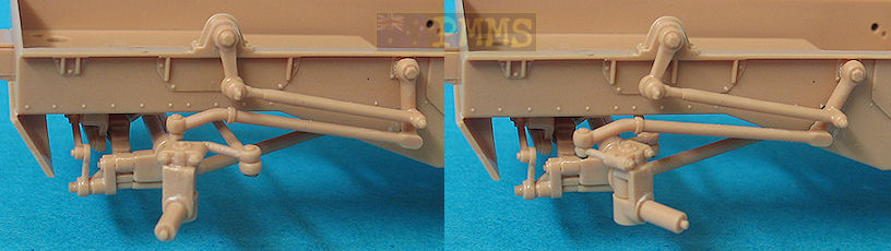
Steering with wheels added
Another simple option is to assemble the steering as per instructions but to cut the pin from the front end of steering rod (part B20) and don’t glue the rod to part B10 on the axle assembly. This will allow the wheels to “steer” but the chassis side steering rods will remain fixed.
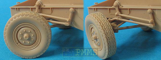
The front wheels have alternate hubs with subtle differences in the details such as rim bulge and number of lightening holes with both types seen in photos of the sWS so there is no real preference here as either can be used. The tyres are in six “slices” each which are sandwiched together for excellent representations of the tread pattern but you have to ensure the segments are put in the right order and also you should squeeze these together tightly when gluing to eliminate any gaps.
The hubs are a nice tight fit inside the tyres when assembled with the final wheels looking excellent with the well defined tread pattern; the only thing missing is any tyre side wall embossing but apart from that are very well done wheels.
Each drive sprocket is made up of three plastic parts and care is needed to clean up the mould seams inside the outer disc spokes and you need to watch the tooth alignment when gluing the inner and outer sprocket discs together.
There are two locating pins between the two sprocket halves and you should test fit these as the teeth only align with the pins one way, if you fit the pins the other way the teeth don’t align so make sure you get the two dish halves aligned correctly before gluing.
Added to the sprockets are etched step rings around the central hub with these having tread plate texturing on both sides for a good impression. It’s best to bend the etched part around a suitably sized drill bit shaft and join the end with a dab of cyanoacrylate. These can then be added to the sprocket hub with the fit being spot on making for a snug fit and this adds excellent definition to the sprocket hub.
As mentioned there two sizes of drive sprockets supplied in the kit and the majority of reference photos of the sWS show the larger sprocket with only one shot I found with the smaller sprocket. This does show both were used but it appears the larger is far more common, it also looks better IMHO.
The recent plans in the new Panzer Tracts book No.22-3 mittlerer Zugkraftwagen 5t (Sd.Kfz.6) and Schwerer Wehrmachtsschlepper indicate the larger drive sprocket is a little over 1mm too small in diameter, this doesn’t sound a lot but could be the reason the Friulmodel metal sWS tracks (Set # ATL44) don’t fit well due the smaller tooth pitch on the undersized diameter sprockets. If you use the kit tracks this won’t be an issue so I guess it’s up to the modeller if this is something to worry about.
The road wheels are the early solid dish type with 5 small cut-outs and these are well done with excellent hub details and good dish profile. Assembly is quite straightforward but I did have to enlarge the locating hole on the inside of the outer wheel (parts A25) slightly to better fit over the end of the axles. You just need a couple of twists of a 1mm drill bit to enlarge the hole but be extremely careful you don’t drill right through the outer wheel hub in the process.
At the back are alternate 2 part idler wheels, the initial spoke type and the later solid dish type with references showing the spoke type are more commonly seen so check if you are building a particular vehicle as to the idler type used.
While the links are not workable they are large enough for you to drill and add a 5mm wire pin at each side to make them workable if you wished.
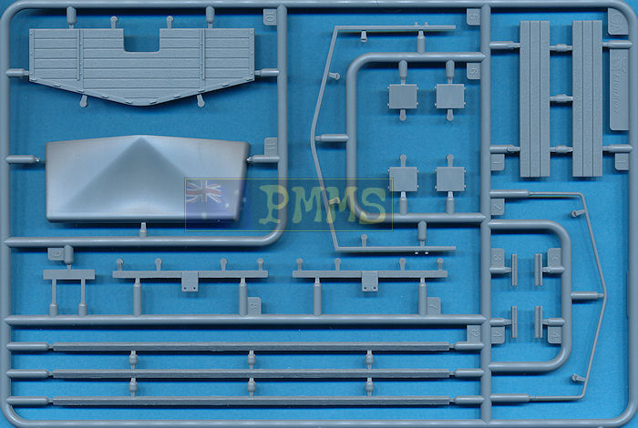
There are small sink marks on top of the two gear levers to fill and the steering wheel is fitted to the separate steering column that extends to the chassis mounted steering box. The seats are in three parts each and the floor has subtle tread plate included to give a good overall appearance.
Added to the fenders are the pioneer tools with moulded on clips, the two front head lights with clear lenses and two part Notek light and the width indicator posts with a mirror on the left post.
Under the left fender is a three part exhaust muffler with the end of the short pipe hollowed out for a better appearance and two bumper bars are added to the front.
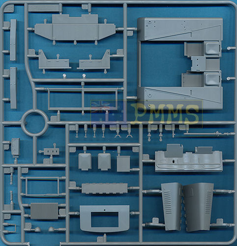
The front radiator coaming has an opening for the radiator which is a separate part added from inside with fine grill texturing as well as an etched number plate added to the lower front. The fit of the radiator coaming is little vague and care is needed to fit this correctly to line up with the folding hood panels, temporarily fitting the hood side panel as you attach the coaming will help getting the correct height for the coaming.
The top hood panel fits between the front radiator panel and the firewall with all the panels fitted either side. The fit was good but you need to make sure the central hinge panel (part GB20) is fitted exactly centrally as this can affect the fit of the hood panels if not aligned correctly resulting in some minor trimming needed.
No engine is included but you could add the sWS engine set just released by Great Wall (Kit #L3522) which is the same engine/transmission included in the recent Bronco Models 15cm Panzerwerfer 42 (Zehnling) auf sWS (kit #CB35070)
A separate canvas cover is supplied for the cab should you wish to add this but the available photo of this vehicle shows the cab roof in the folded position with the cab is fully exposed offering potential to fully detail up if you so wish. The fit of the cab to the lower chassis is very good with small locating pins resulting in no filler or trimming being required.
The interior includes a separate instrument panel with decal dials, radio and small lever box with three very small levers added to the driver’s side as well as the three separate foot pedals and three gear levers for a fairly well populated compartment. The seats are in three parts each and the floor has subtle tread plate included.
Added to the underside of the floor are long mounting beams for fitting to the lower chassis and there are locating recesses on the floor underside to make for a good alignment with the chassis frame.
Other smaller fittings to the cargo tray are the rear number plate bracket and tail light and two pioneer tools which have moulded on tool clips added to the real gate with the fit of the assembled cargo tray to the lower chassis being spot on and trouble free and this allows you to paint the sub-assembly separate and add later in the final assembly.
To fit the 3.7cm FlaK 43 you are required to drill a number of holes into the tray bed to attach the gun mountings and there is a plan drawing in the instructions with measurements for the hole placement, this is not 1/1 scale unfortunately so can’t be used as a straight template for drilling the holes.
The main issue here is the instructions show to drill the holes the wrong way around on the bed, by this I mean if you drill the holes as indicated the gun will be mounted towards the back of the cargo tray and not forward as on the armoured sWS 3.7cm FlaK 43. There are a couple of issues arising from this, one the weight distribution is all wrong with the full weight of the gun over the rear few road wheels and not mounted centrally over the suspension on the armoured sWS 3.7cm FlaK 43 and all other half-track 2cm or 3.7cm FlaK vehicles. The other is the available photo of this vehicle clearly shows the gun mounted in the forward position, it is traversed with then gun facing the rear of the vehicle which may be the reason for the confusion?
This is easy to fix by simply making the measurements indicated in the instructions with the tray bed rotated 180 degrees so the gun will be mounted forward on the tray bed. After marking the hole positions, test fit the gun triangular base to ensure they match before actually drilling the hole to avoid problems later.
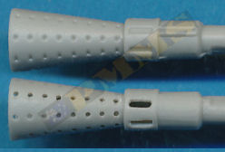
The barrel is in plastic with the correct length and flash suppressor size but this is not fully hollowed out and the neck and suppressor holes are only indentations. Replacing this with a metal barrel will improve the appearance of the flash suppressor considerably but given the size of the flash suppressor it is possible to drill out the holes for an acceptable appearance should you not want to but an AM barrel?
drilling the holes to improve the appearance.
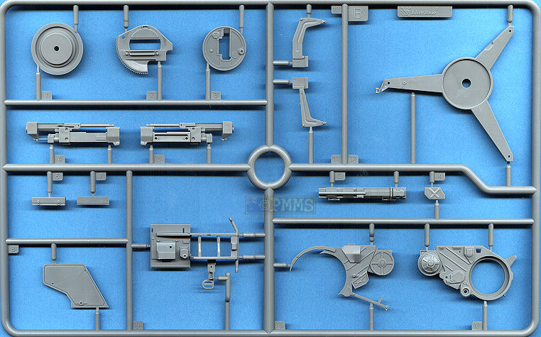
The main gun mounting is in two halves that trap a small pin for the sight mounting and you should be careful not to glue this while fitting the halves together. There were no problems with the fit and added to the mounting is the two part circular gun rotating mount which is fitted from either side of the main mounting allowing it to rotate and again there were no problems fitting these parts.
Added to the mounting is the large side shield moulded nice and thin without any pin marks to contend with.
The lower gun platform has a separate central plate with nicely embossed detail and additional small details added to the platform including the gun travel lock that can be positioned in travel or firing mode depending on your choice for the model?
Added to the gun are the left side ammo feed tray and the side mounted box made up of 7 parts that fit together perfectly without any gaps but mounting this on the cradle will need care as there are only two small mounting points. The kit provides four 37mm round clips that can be fitted to the ammo feed chute or mounted on the box as you wish.
On the right side is the lower two part tray and the traverse and elevation hand wheel mounting which has two of the smallest plastic parts for the star fasteners you are likely to find and extreme care is needed when handling these or they will disappear. There is also the side spent shell exit chute made up of three parts that fits into the opening in the gun mounting.
There is a nicely detailed main sight that will move with the gun when elevated if you are careful with the glue as well as the two gunner’s seats that fit together without any problems although these assemblies will need care as the parts are quite small.
The main gun shields are in plastic and moulded in a uniform thickness (thinness) without any pin marks to contend with. The instructions indicate to trim a little off the shield top corners for the vehicle mounted gun which shouldn’t be a problem.
The side foldable shield sections and the sight doors are separate parts and can be fixed in the extended or closed position depending on the kit finish. There are small plastic securing latches and the gunner’s foot rests to add to the inside of the shields with the assembled shields fitting easily to the lower cradle mountings.
The final item for the gun is the large mesh spent shell container fitted to the right side during firing and this has plastic frames to which is added very fine etched mesh and annealing this with a candle flame will allow a less rigid and more realistic appearance once assembled.
The three legged platform matches available photos well for size and the fact that each leg is a different length with the lifting hooks on the end of two legs being separate parts. There are additional smaller etched details to be added but everything went together quickly and easily ready for the gun to be fitted. A small underside bushing attaches the gun to the platform permanently to allow easy traverse but you need to make sure this bushing (part N9) is not glued to the platform if you want the gun to traverse.
Great Wall Hobby provide an etched update set #L3516T for this kit that includes full brass shields and set #LB3514 with a metal 37mm barrel plus numerous other companies producing metal 3.7cm FlaK43 barrels should you want to add further detail?
The overall quality of the kit is very well done with the basic sWS vehicle featuring some excellent details such as the engine bay door louvers, driver’s compartment interior, rear cargo tray as well as being mostly dimensionally acceptable overall. There is very little cleanup required and the fit of the parts very good overall with the front wheels and running gear/track being especially well done.
The inclusion of the 3.7cm FlaK 43 with the standard cargo body makes for an interesting variation and building a diorama with this vehicle and the armoured sWS w/3.7cm FlaK 43 as per the period photo is a very attractive proposition.Rating: 8.5/10.
Click on thumbnails for larger view


Detail Images

| Büssing's schwerer Wehrmachtschlepper (sWS), armored and unarmored variants Nuts & Bolts Vol.41  |
mittlerer Zugkraftwagen 5t (Sd.Kfz.6)
and Schwerer Wehrmachtsschlepper Panzer Tracks No.22-3  |
Halftrack Vehicles of the German Army 1395-1945 Schiffer Military History ISBN: 0-88740-758-7  |
German Medium Half-Tracked Prime Movers 1934-1945 Schiffer Publications ISBN: 0-7643-0263-9  |
| Flakpanzer IV Wirbelwind (Sd.Kdz. 161/4), Ostwind & Kugelblitz Nuts & Bolts Vol.25  |
Flakpanzerkampfwagen IV and other Flakpanzer projects from 1942 to 1945 Panzer Tracks No.12-1  |
 for
the review kit.
for
the review kit. 