
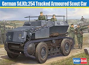
German Sd.Kfz.254 Tracked Armoured Scout Car
Hobby Boss 1:35th Scale Kit No. 82491
Review by Terry Ashley
The RK-7 was powered by a 4-cylinder Saurer Diesel Typ CRDv engine of 5500cc generating 70bhp for a top speed of 30km/h (tracks) and 60km/h (wheels). With the annexing of Austria into the greater Reich in 1938, 140 vehicles were ordered with the German designation Sd.Kfz.254 Armoured Observation Vehicle but only 129 were completed with armoured bodies by Dailmer-Benz before production ended in favour of the Sd.Kfz.353 and Sd.Kfz.250/5 half-track observation vehicles.
The Sd.Kfz.254 saw service in the early war campaigns in Poland and France as well as in North Africa, the Balkans and Russia.
- 196 parts in light beige plastic
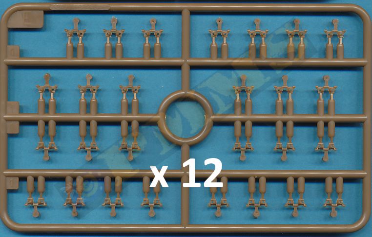
- 324 individual track links in brown plastic
- 60 etched brass parts
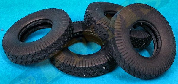
- 4 vinyl tyres
- 1 decal sheet
-
1 16 page instruction booklet
Etched and clear parts
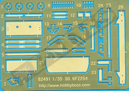
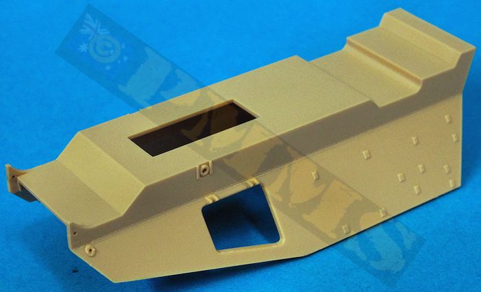
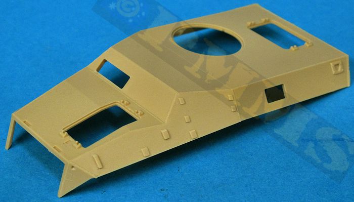
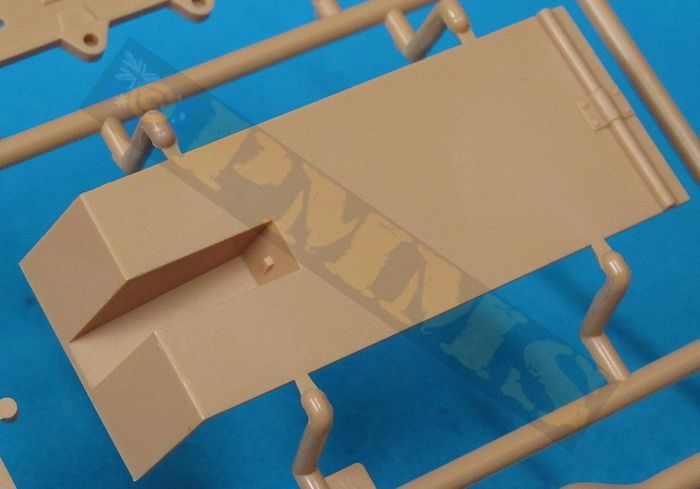
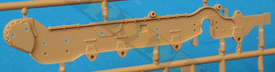
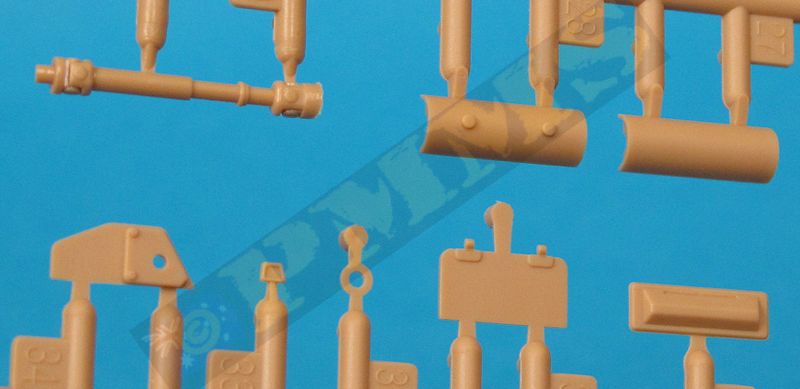
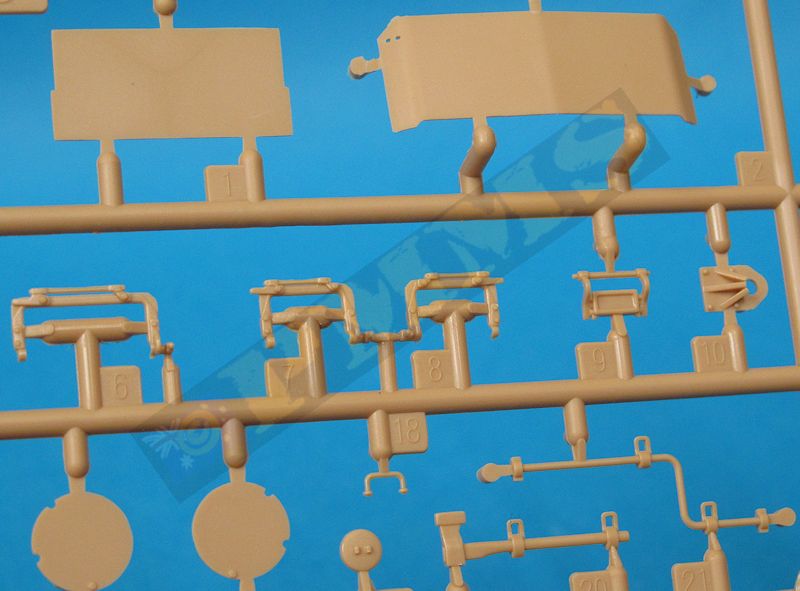
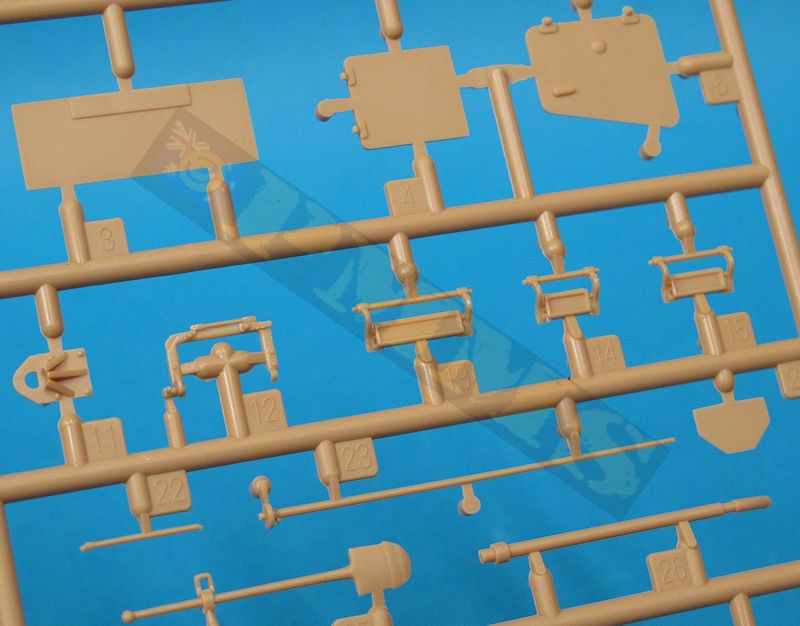
The standard of moulding is very good with clean crisp details and very few if any pin marks or other blemishes with the only clean-up being the usual mould lines and the many small nodes. Surface details are well done with hull weld seams and engraved lines cleanly done as are the numerous bolts and rivet heads. All the hull hatches and vision blocks are separate parts although there is no interior included apart from the inside visor frames and the suspension is especially well detailed with the etched parts providing additional nice details around the hull.
Dimensionally the kit matches the 1:35 plans in the Nuts & Bolts book very well in all major areas with just some minor discrepancies, the most obvious being the large wheel rims being a little over 1mm too small in diameter, this doesn’t sound a lot but the visual effect when looking at period photos exaggerates the differences in sizes.
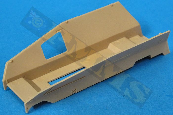
The hull bottom plate fits neatly between the chassis sides as does the front curved bulkhead with the fit of all these parts not requiring any trimming to fit. The real plate has the two large entry doors as separate parts but as there is no interior these are best glued in the closed position. The rain guard above the doors in an etched strip that has small curves added at each end as well as separate number plate. The fit of the rear plate to the hull is very snug and again no trimming or filler was required for a good fit.
The track suspension bogies have single road wheel front and rear bogies and two double wheel bogies and these assemble easily with good detail, although the springs appear a little undersized but nothing to get excited about. You just need to take care to assemble the bogies as per the instructions as there are some parts that look the same but have small differences. The road wheels can be left free to rotate if you wish otherwise glue these to the bogies for more robust assemblies. The bogies fit snugly to the chassis and the first three bogies units are joined together by a long side bar with the three return rollers also fitting nicely to the chassis mountings for relatively trouble free assemblies.
The car wheel suspension is another deal altogether, the front wheel station wishbone arms and mountings are separate parts and assemble into a sub-assembly that has the wishbone arms fully movable. The rear wheel station has two small support arms and the large wheel hub that again assemble into a fully workable sub-assembly to allow the wheels to be raised or lowered as per the real thing. Fitting these to the chassis sides by way of small brackets is rather tricky due to all the moving parts that have to be fitted into locating holes at the same time and care is needed.
The wheels can be assembled in the raised or lowered position but you have to make a choice as there is no actual indication or locating points to fit these in the right position and the wheels suspension has to be firmly glued into the required position, this is best left till last after the tracks have been fitted to get the correct ride height for the lowered wheels as it’s difficult to get this right before hand, but more on this later. The rear wheel station hubs are attached to the large rear differential axle added to the underside of the hull and this can be moved to align to the wheels either in the raised or lowered position depending on your choice.
The four large car wheels have two part wheel rims and the vinyl tyres that have nice diamond pattern tread but no sidewall data embossing, the main issue here as mentioned above is the rims are a little over 1mm too small in diameter but the tyre diameter is correct. The rims also lack the air valve and the size difference may not seem much but it is quite noticeable visually when comparing to the period photos. The wheels themselves fit neatly to the wheel hubs but can’t rotate after assembly.
Added to the rear chassis is the tube chassis cross member and idler axle mountings made up of five parts and this fits neatly to the chassis frame for a precise and solid fit with the two towing hooks are added to the cross member.
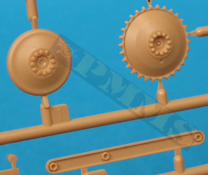
The final drive housings fit to the hull front and the single tooth drive sprocket fits neatly to the final drives, the sprockets are the correct diameter with the correct 30 drive teeth and nicely defined central hub bolts for well-done sprockets. The dished idler wheels are also the right diameter with also good rim bolts but the idler axles are fixed in position on the rear chassis meaning you can’t make any adjustments for track tension if required.
Added to the rear chassis frame is the crew entry step provided in etched brass (part PE-26), this is easily bent to shape but the instructions at step 6 show this fitted upside down and you should fit this the opposite way up as correctly shown in step 12. At the front are the two towing hooks and lower guard plate as well as the honeycombed radiator mesh (in solid plastic) with the three spring radiator attachment bolts made up of two etched and one small plastic part each. These attachment bolts are very well done it’s just a pity they are completely hidden after assembly by the front armour plates.
Each track link has three sprue attachments that takes a bit of clean-up but there are no pin marks or other blemishes although the detail is a little heavy such as the guide horns. Due to the small size fitting the links together is a little fiddley at times as you have to glue each of the 136 links per track run together as you go to prevent them falling apart. Note, the instructions show to use 138 links but I only needed 136 for the completed track run on the review kit. It is actually quite difficult to get the links in a perfectly straight run due to the small size while fitting and the whole process was very time consuming and a little frustrating.
The fit of the upper hull to the lower hull is very good at the front and along the sides where there is the small overhang but the fit at the rear top join left a large gap, this was so large I went back to fully check the location of the rear hull plate and the top hull but these were all positioned correctly so this gap is quite alarming. It would be best to fill this with plastic card strip as it’s too wide for any type of filler and trimming the plastic strip once dry should alleviate the need for filler given the gap is quite even across the hull.
Once this is attended too the remaining hull items can be fitted these include the front cover plate that has an etched ducting plate that needs careful bending to the curved profile and when fitted covers the nice spring radiator attachment bolts mentioned above. There is also an air scoop added across the top of the hull nose and the edges are a little thick and it should be noted this was a later modification so may not be applicable for all vehicles and checking references if available will show if its fitted.
The large outer nose armoured plate (part B2) has four etched mounting brackets attached to the nose sides but the outer curved sections are to short and should extend further around the nose, this may have resulted from the head lights being positioned slightly too far forward on the hull and not leaving enough room for the correctly sized armour panel? The head lights themselves have separate plastic lens covers and thin mounting post but the lights are undersized by about 1mm in diameter which may not be that bigger deal.
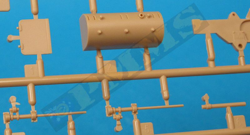
On the left side is the engine hull extension and four part exhaust pipe, this assembles easily but you may want to drill out the end of the pipe for a better appearance. There is an etched mounting plate and rear mounting bracket for the muffler and pipe, note with the mounting plate (part PE-3) the edge bends should be made away from the engraved lines and not into them as is the normal manner with etched parts.
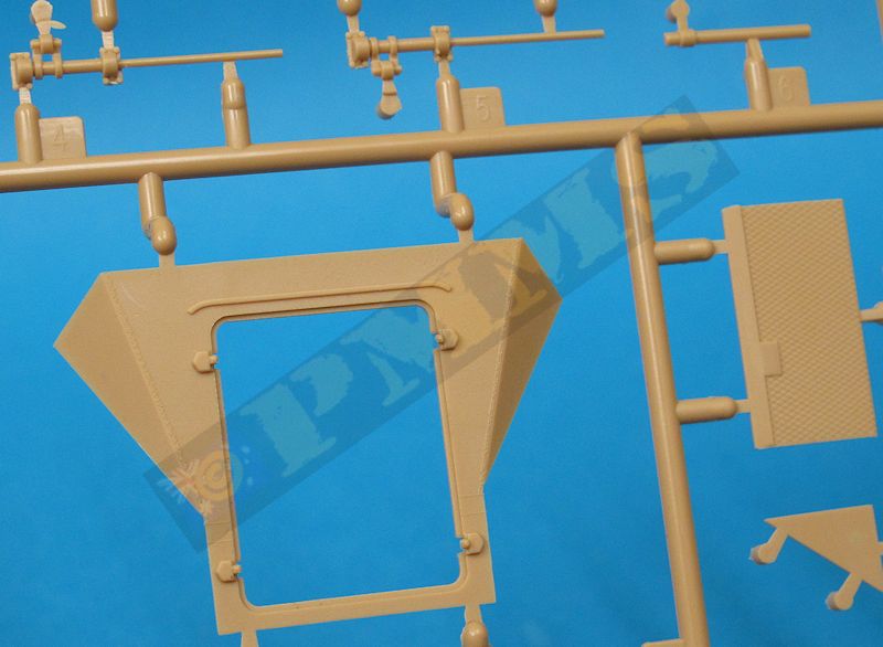
The right side crew entry door can be shown open or closed with an internal door brace if open but again as there is no interior gluing this closed would be the best option unless including a crew figure? Added to the hull sides are the pioneer tools and etched mountings for the turn indicators and antenna tray, all these have raised attachment blocks moulded with the hull which is correct but the tools also have quite hefty lugs on the back of the moulded on clips that see the tools sitting way too far out from the hull. Either trimming to tool locating lugs or replacing the moulded on clips with etched items would give a better appearance.
The turn indicators have etched outer faces for a nice appearance and the long front width indicator posts need care after fitting as they just hang out there asking to be broken off and there is the Notek light with etched mounting bracket added to the front armour plate, note care is needed when trimming the sprue attachments on the Notek light to preserve the lip around the light.
The large frame antenna is fitted to the roof, the antenna is quite thin and care is needed removing the two segments from the sprues and in cleaning up the fine mould lines with the four posts having open holes at the top for a very precise fit. After gluing the posted to the roof along with the small etched roof attachment plates you can insert the antenna through the post holes initially without gluing until it is aligned correctly, this makes the assembly very easy with the front section of the antenna angled down slightly. The large rear antenna is designed to be glued raised and some minor trimming of the base will be needed to show it lowered into its storage tray.
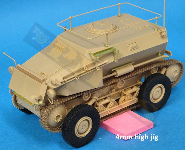
The distance between the bottom of the tracks and the ground line is 4mm in scale and sitting the tracks on a 4mm jig and then gluing the wheels and suspension so they meet the ground nice and vertical is the easiest option. I actually used sticky notes for the jig as this allowed me to add or remove notes to get the correct height very easily. Once the glue has fully dried the jig can be removed and wheels are at the correct ride height, fitting them in the raised position is a bit hit and miss with the wheels raised as far as possible before gluing using period images as guide.
Once glued in place the front wheels have a wider track (width) than the rear wheels which is correct, this leaving clearance for the front steering on the actual vehicle.
Option 1:
WH-800920 3.Batt., I.leichte Abtlg., mot. Artillery Regiment 119, 11th Panzer Division, Balkans 1941. Option 2: WH-616663 4.Batt., II.leichte Abtlg., mot. Artillery Regiment 33, 15th Panzer Division, North Africa, 1942.  Option 3: WH-616658 6.Batt., II.leichte Abtlg., mot. Artillery Regiment 78 ,7th Panzer Division. (this option not listed on the instruction sheet) Note; the 7th Panzer Division Y is done in white on the sheet but should be yellow. Front views in the GP magazine listed below showing the markings placement. 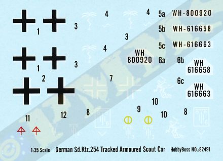 |
The only real areas of concern are the car wheel rim and head light sizes and the large gap at the rear roof join that will need a bit of work to eliminate. The main thing to watch is the fixing of the car wheels in the lowered position due to the absence of any precise fitting guides basically leaving it to the modeller to get right.
As with any kit there is room for adding additional details and the Nuts& Bolts books has some excellent close-up shots of the surviving Saurer that provide most if the smaller details that can be added.
Rating 8/10
Click on thumbnails for larger view
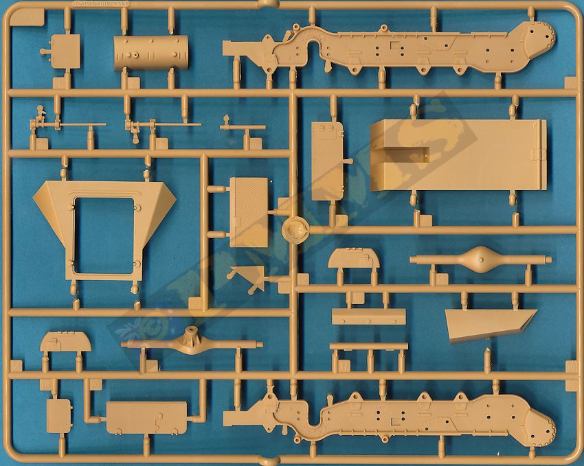
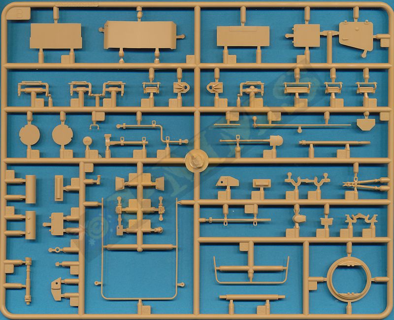
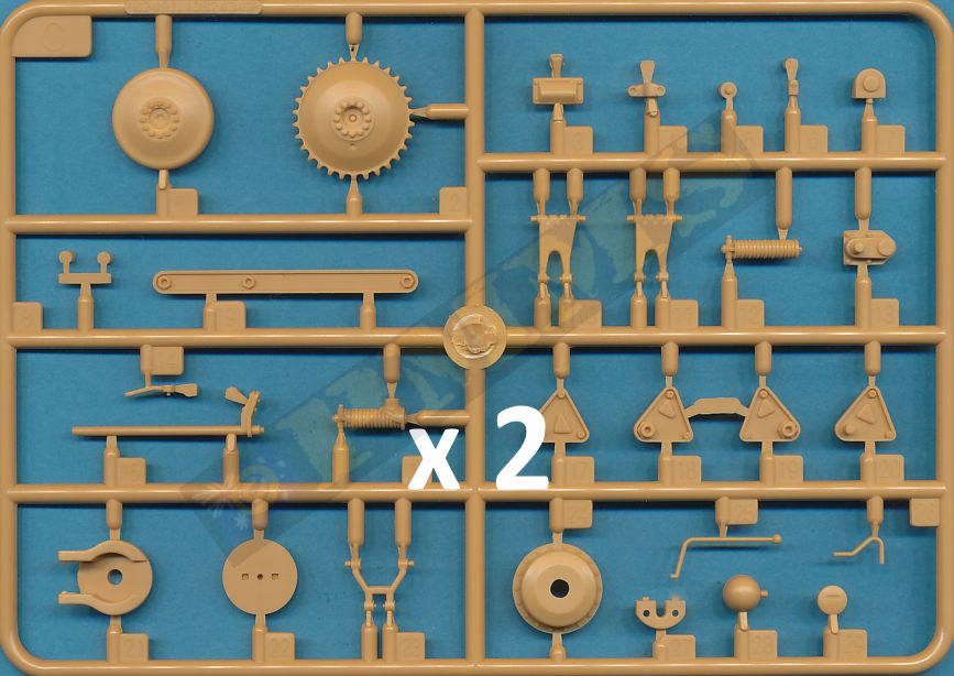
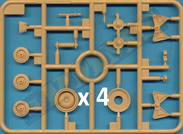
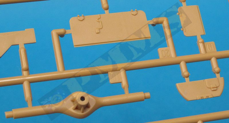
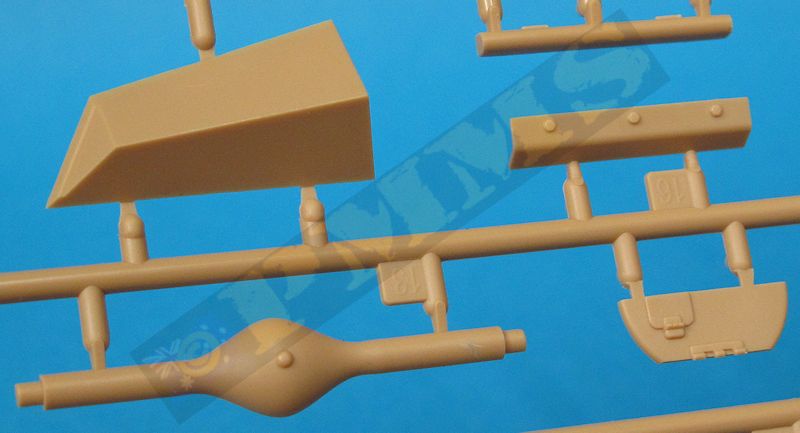
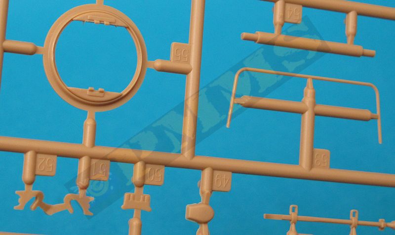
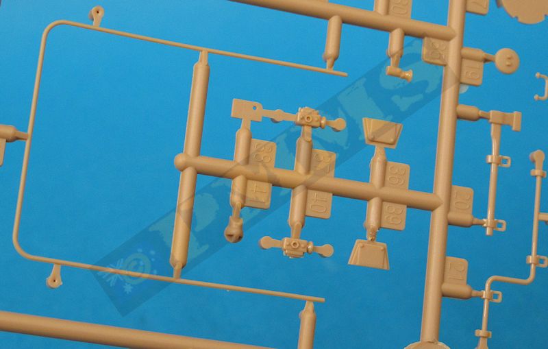
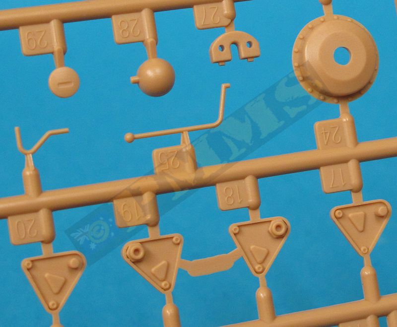
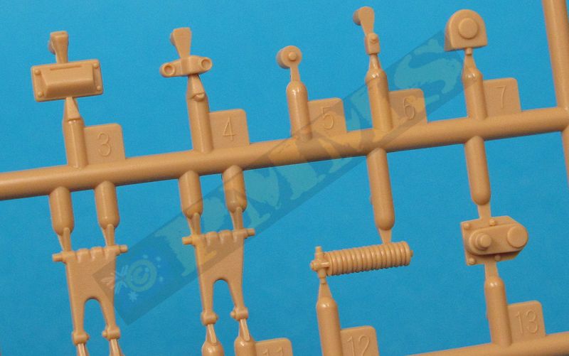
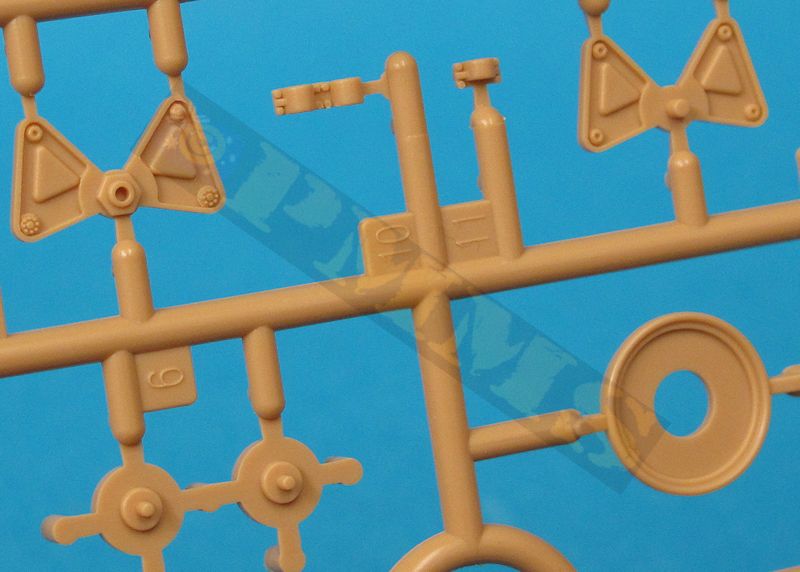
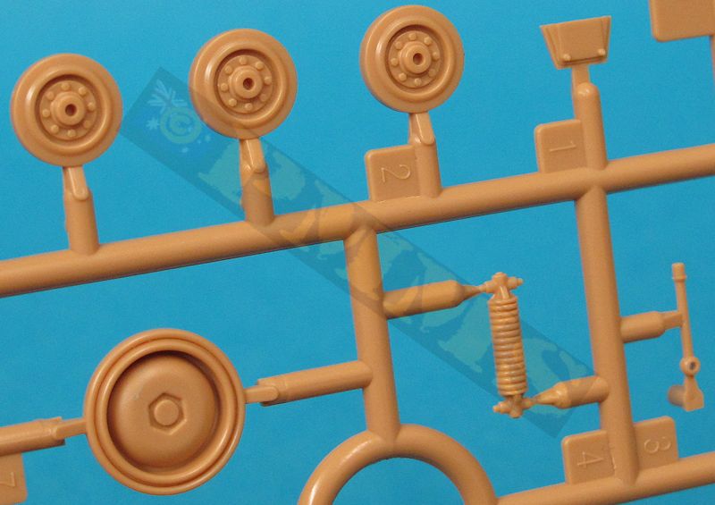
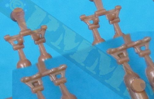
Sprue Detail Images

| Saurer RK-7 (Sd.Kfz.254) Nuts & Bolts Vol.5 John L. Rue  |
Ground
Power Magazine #219 - 8/2012 GALILEO Publishing Co.,Ltd  |
Thanks to my credit card for the review kit.
