
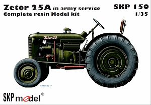
Zetor 25A Tractor
in army service
SKP Model 1:35 Scale Kit No. SKP 150
Review by Terry Ashley
Between 1949 and 1961 a total of 158,570 tractors were produced at the Brno factory in Czechoslovakia (Czech Republic) with many still in use even today.
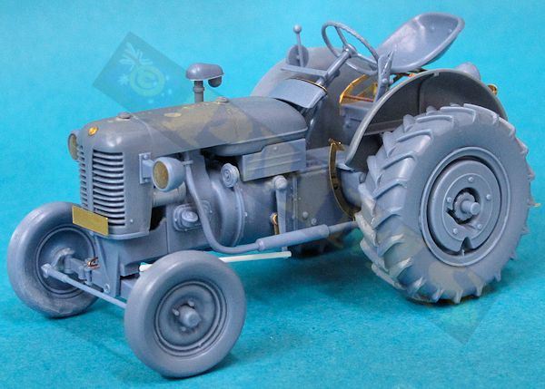
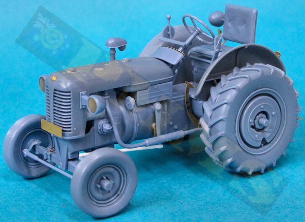
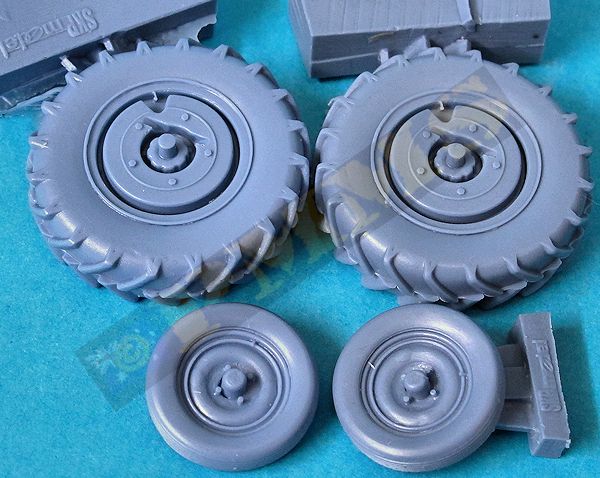
There is also the low slung exhaust pipe of the earlier Zetor 25 but again references indicate the top mounted exhaust pipe was used with the Zetor 25A but this isn’t included in the kit unfortunately. The large rear wheels also have a fully enclosed wheel rim and this is seen in a number of photos of the Zetor 25A and is most likely a modification for the military use as civilian tractors have an open spoke design for the rear wheel rim.
The kit can be called a true multi-media kit that consists of:- 61 parts in a blue/grey resin
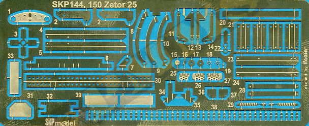
- 47 etched brass parts
- 82 small etched hex bolt heads
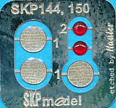
- 5 resin headlight/taillights
- 1 photo film instrument dials
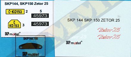
- 1 small printed sheet with number plates
- 1 small decal sheet
- 12 page A5 sized instruction booklet.
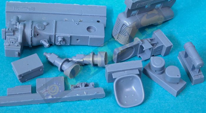
The standard of resin casting is excellent with clean crisp castings with just some minor resin film and the usual casting plugs to be removed. There is one area that will need more attention with the casting plug on the engine top cover/radiator located along the top of the cover and when removed exposes a number of holes and imperfections on the cover. The holes will need to be filled and sanded along with the imperfections to get a smooth top surface for the cover, the degree of blemishes here will differ on each set due to the nature of resin casting but this was the only area requiring any additional clean-up.
The etched brass is done by Hauler so is of top quality with bending lines and other small marks showing where to fit the parts and using a good bending tool for the longer chassis beams will help while flat point tweezers will suffice for the smaller bends.
Clean-up of the resin parts was quick and easy due to the relatively small attachment points for the casting plugs even on the larger parts and the resin is easy to work with not being overly hard or brittle but you still need to take due care during the clean-up process. Many of the parts have small locating pins and corresponding holes for better fitting but a few of these needed the locating holes slightly enlarged so test fit before gluing.
The only fit issue was with the alternator (part A48) as this will prevent the top engine cover from fitting if added as it comes, I had to trim the section of the alternator that overlaps the engine block to about half thickness so the alternator will be closer to the block leaving clearance for the top cover but more on this below.
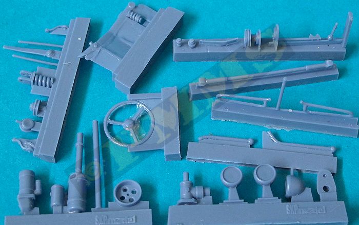
The front axle is cast with the axles fixed in the neutral position but it wouldn’t be too much trouble if you wanted to alter the angle of the front wheels. There are a few small steering parts added to the main spring that need care and when fitting to the underside mountings ensure the spring is fitted perfectly centrally as there are no actual locating holes. The two support rods (parts A36) will need trimming to fit so test fit to determine the correct length.
Other items added are the steering column, the low slung exhaust pipe, this can be drilled out for a better appearance and the long steering rod and smaller clutch linkage rod have to be sourced elsewhere which shouldn’t be a problem. The left side tank (part A18) is rarely seen in period photos and can probably be left off.
I used thicker cyanoacrylate to assemble the frames as they don’t take any stress after assembly but you could also solder the parts for a more robust assembly. When assembling the two side frames it is important to fit everything perfectly square, there are small marks on the parts to ensure the correct placement, you have to supply the thin wire needed in the side frame boxes and there are 14 hex bolt heads added to each side frame to finish off.
The rear tow bar frame is also quite straightforward being simply angle bends and again it’s important to get everything nice and square with the spring tow shackle in resin added. The tow bar frame can be attached to one side frame again ensuring it’s all square before fitting to the drive shafts to make things a little easier.
The side frames are fitted around the square drive shaft sections and before actually gluing in place fit the cross member (parts L20, L30) to get the right spacing, again without labouring the point make sure these are fitted perfectly square for a good fit. The rear perforated cross member (part L30) is bent back over itself for a thicker part and this should be bent with the engraved bending line on the outside not on the inside as is the usual practice.
When you are happy with the alignment of all the frames you can glue them to the drive shaft square sections for finish the assembly with the etched frames having an excellent appearance when done.
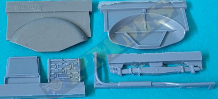
The cushion seat is a far simpler affair with just the seat and backrest with textured cushions, the backrest also has spring detail on the back plus the lower mounting frames, the attachment of the backrest frame to the two lower mounting frames (parts A25, A28) is just a butt join and not very strong and I inserted small wire pins in the frames for a more robust assembly. The two cross members (parts A26, A27) may need trimming for a better fit with the desired seat added to the lower storage box before being fitted to the top of the rear transmission.
The engine top cover has the radiator front included and this has open front grills with just some very fine resin film to be trimmed which is easily done with a sharp #11 blade and a small box added to the underside. As mentioned above there was a fit issue with the engine alternator and as well as modifying the alternator the sides of the radiator cover had to be thinned considerably to allow proper clearance, this also improves the appearance in the process. Also the inner front corner of the underside box needed to be trimmed to fit the curve of the transmission housing and on the right side the air intake pipe had to be trimmed a little to fit under the top cover and test fitting along the way will determine the trimming required.
The two large rear wheel fenders are easily fitted to the side frames along with the head lights with the resin lens inserts added, at the back is another large head light that is located differently depending on the seat used and the small tail lights. Note there are alternate lights and number plates that may not be used on all tractors but the small red resin taillights add a nice touch to the appearance.
Finally the front and rear wheels can be added, the front wheels have nice subtle tread pattern and hub detail and the larger rear wheels have the larger tread pattern well done with the hub detail well defined, as mentioned this probably the military design hub as the civilian hub is an open spoke design. The casting plug scar on the wheels can be positioned at ground contact to hide nicely.
-
Zetor 25A, state farm Kolin, 1952.
- Zetor 25A, Czechoslovak People's Army, Mlada Airfield, 1953.
As far as resin/etched kits go this is fairly simple and offers the opportunity to hone your skills working with resin and etched brass for the less experienced as most of the sub-assemblies are fairly straightforward compared to some more complex kits.
The only real detail issue is the low slung exhaust pipe with references indicating the larger top exhaust would be more appropriate for the later Zetor 25A tractor, this would be easy to make from plastic rod should you wish to make the altertation.
The end result is an impressive little kit of an unusual subject that provides a nice alternative and can be used in basically any post war eastern European scene.
Rating 8.5/10
Click on thumbnails for larger view
Resin part images
Detail Assembly images

- The Wonderful World of Vehicles-Zetor Model 25 A
- TractorData.com-Zetor 25A
- Zetor 25 A
- Zetorworld
- Various online images-Google
Thanks to SKP Model for the review kit.
