
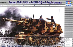
German 39(H) 10.5cm leFH18(Sf) auf Geschutzwagen
Trumpeter Kit No. 00353
1/35th Scale
Review by Terry Ashley


This kit consists of 227 parts in light beige plastic plus two full length “rubber
band” type vinyl tracks and a small decal sheet. The quality of the moulding
is overall quite good but there are some pin marks on a number of parts that
will need attention, such as on the insides of the superstructure walls and
on the back of the road and idler wheels but these can be positioned facing
inwards and out of sight.
The kit shares the same lower hull tub, running gear and track as the other
H39 kits with three new sprues (E,F,G) for the leFH18 and superstructure parts.
Note; the kit has only been assembled with the major components to show any issues that arise and the finer parts such as the tools, lights etc. have still to be added.
Lower Hull / Suspension:
The lower hull tub has the front and rear panels included and at the front
is the large HOTCHKISS name casting which is very prominent on these vehicles
while on the inside is floor details and a rear bulkhead to help keep everything
square. The final drive housings and idler wheel mounts are separate parts
as are the two return rollers per side plus simple attachments points for
the suspension bogies.
The six suspension bogie units are made up of eight parts each with quite good details but the upper springs are a little fine and some may wish to replace with thicker wire for a better appearance? The drive sprockets include the characteristic dome shape but unfortunately the central bolt heads and drive teeth are undersized but may not be that noticeable on the finished kit?
There are two idler wheels provided, one with ribs and the other smooth and the instructions indicate to use the ribbed wheels on the kit but I’ve seen photos with both types so you have choice here.
 Construction
of the bogies was a little tricky as there is no actual locating point for
the top mounted springs and these were simply glued to the rear bogie plate
at the appropriate place level with the moulded on attachment bolts on the
outside of the bogie plates.
The wheels are designed to rotate when trapped between the front and rear bogie
plates but there are only a couple of small attachment points for the two bogie
plates and the top brackets (part A15) have to be positioned over the two bogie
plates at the same time as positioning the wheels which was all very tricky
and I ended up gluing the wheels in place which made for a mush more robust
assembly and as the drive sprocket and idler wheels are only designed to be
glued in place gluing the wheels is not an issue. What is an issue is the fitting
of the bogie units to the hull, the locating pin on the hull fits into the
corresponding hole on the back of the bogie bracket (part A15) which also has
a small L bracket to fit under the bottom of the hull for support, unfortunately
the hole on part A15 didn’t line up precisely with the pin on the hull
and required some trimming of the bracket (part A15) to get the bogies to sit
correctly on the hull, this isn’t a real hassle as after trimming the
bracket they then fitted okay and at the same height.
The lower hull tub has a basic interior with rear engine bulkhead and drive tunnel to the front gearbox and a basic driver’s seat and this forms part of the interior once the new superstructure is fitted and can be assembled as per instructions without any problems.
The leFH18 Howitzer:
 This is quite a nicely detailed gun with plastic barrel split vertically and
a separate four part breech and breech block that allows it to be positioned
open or closed and a large double baffle muzzle brake in two parts. The breakdown
of the gun parts has the cradle in two halves with nice bolt head details
and left and right lower cradle with the two supports for the upper recuperator
as well as the hand wheels and well detailed gun sight.
The side mounted recoil cylinder is moulded in one part with a separate lower
piston that fits into the hole already in the cylinder and will move freely
after assembly so the gun can elevate as required. There are a couple of pin
marks on the recoil cylinder and one on the upper recuperator that will need
eliminating but other than that there were no other cleanup issues.
Assembly was straightforward without any problems on the gun itself but there
were a couple of issues with the new front shield, armoured carriage and recuperator
housing.
The front part of the carriage is armoured and is moulded separate from the
rear carriage designed to fit to the front of the central gun shield (part
G45), this is moulded rather thick and has some pin marks on the back to be
removed. The upper recuperator housing (part G41) doesn’t fit into the
recess in part G45 and it is easiest to just position this so it lines up with
the lower carriage rather than try and enlarge the recess, which is only going
to arrive at the same result anyway. Also note the two small fittings (parts
G29, G30) on either side of the part G41 are numbered incorrectly in the instructions
and part G29 should be G30 with part conversely G30 should be G29.
The locating hole in the top rear of the shield for the recuperator cylinder had to be drilled out as it was too small for the cylinder and the shield and front part of the carriage (part D) is then attached to the main gun assembly and barrel ensuring everything lines up correctly. The muzzle brake can now be attached to the barrel but don’t fit this earlier or you will never fit the barrel through the gun shield.
The front lower shield (part F27) is actually attached centrally to the lower carriage assembly and not to the barrel as shown in the instructions with the fitting of this part being very vague in the instructions and care should be taken with this.
The lower gun mount is straight forward and this is attached to the hull interior side sponsons later and can be left separate from the gun at this stage.
Superstructure:
 The
two main superstructure walls are moulded as one piece which eliminates any
join seam problems but there are quite a few pin marks but thankfully only
two are visible after all the inside parts are attached. The inside of the
rear panel and separate doors also have substantial pin marks that have to
be filled as they are all visible after assembly.
On the inside of the side walls are separate inner panels for the front walls
to replicate the spaced panels with accessories added while on the walls are
the large rear ammo boxes and MG ammo racks plus the large radio rack on the
left wall. A couple of things to watch here is that the top rear of the right
hand ammo box needed bevelling to fit properly against the wall and the small
bracket on the rear of the left ammo box needs about 1mm trimmed to allow the
engine compartment floor to fit properly.
At the front of both sides some trimming of parts was needed to allow the proper
fitting of the inside front panels, on the left part F17 was trimmed to miss
the radio and on the right the end of the MG ammo rack was trimmed to miss
part F22.
Careful note should be taken as to the location of the side brackets (parts
F32 and F21) as it can be a bit confusing where they should go.
After adding the interior parts you then fit together the two side panels, real panel and engine compartment floor and after trimming the bracket on the left ammo box these parts fitted together very well with no apparent gaps or other issues. One thing I did do was fit the front driver’s plate (part F30) at this point to ensure the correct alignment of the side panels, also note that part F31 fits above part F30 at the front.
The fenders were then added to the bottom of the superstructure assembly and again these fitted well without any issues and the gun mounting platform was also glued to the inside sponsons and allowed to dry.
Final assembly:
 The
fit of the assembled superstructure to the lower hull tub was again very good
without any gaps or other issues and the front glacis plate was added which
required the front join seam eliminated and there were two slight gaps either
side between the glacis and superstructure that will need filling. At the rear
the exhaust pipe was a hit and miss affair with no locating points and one
exhaust “leg” hung out over the rear hull contours with no where
to go and some minor trimming was needed on the bottom of the “legs” to
get a flush sit on the rear panel.
The gun was attached to the mounting plate and stayed in place without glue
allowing traverse if required and the two side gun shield hinged plates were
added, these have small pins on the back that fit into holes on the front of
the superstructure that obviously means the gun is fixed so if you want the
gun to move simply cut off these locating pins. It was easy to remove the gun
assembly at any time that will help with painting and the MG34 mounting on
the right wall is fitted, the MG34 is okay but not as detailed as the weapons
in the AFV Club and Dragon Sd.Kfz.251 kits released recently.

Additional items such as the pioneer tools are added around the vehicle and as with most kit tools will benefit from etched tool clips, while the NOTEK light is very basic and could do with replacing as is the rear tail light and finally the rear fenders are added
As a bonus there are two standing crew figures included, a Commander and gunner figure that have quite good details and could be posed inside or outside of the model.
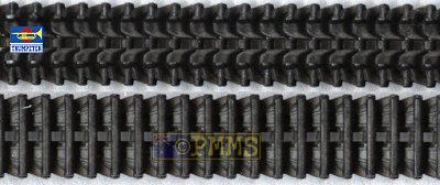
Tracks:
The tracks are full length vinyl and have quite well defined details on both
sides and should look okay on the finished kit, the instructions show to fit
these before attaching the upper and lower hull parts as there is not a lot
of room under the fenders is fitted later.
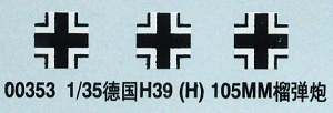
Decals:
The small decal sheet has three German crosses only with no other markings
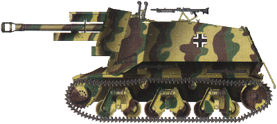
with two three colour cam schemes shown on the instruction sheet.
Conclusion:
Overall a nice little kit with mostly good fit of parts and a nicely detailed
leFH18 and while the kit has most of the basic items there is much scope for
additional detailing inside and out.
The kit should be welcomed by German vehicle fans and it remains to be seen how
it stacks up against the soon to be released Bronco Models kit.
Recommended.
Click on thumbnails for larger view


Close new window to return to review
References:
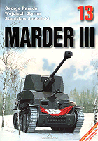
Marder III
Kagero Photosniper 13
George Parada, Wojciech Styrna, Stanislaw Jablonski. ISBN 83-89088-03-7
Thanks to my credit card and  for
the
review kit.
Page created 5 December 2004