

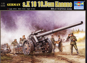
Following closely behind their kit of the sFH18 150mm Howitzer (kit #02304) Trumpeter have now released the earlier s.K 18 10.5cm Kanone which used the same carriage as the 150mm sFH18 Howitzer along with the 10.5cm barrel and breech but it was not a popular weapon being regarded as being too much gun for too little shell and production was ceased in 1943.
Initially it was horse drawn but later versions used a towing vehicle, mostly the 8 ton Half-track and there were some differences in detail between different production batches that show up in photos but the main features remained the same.
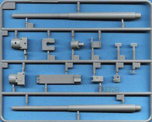
This kit as you would imagine is basically the same as the sFH18 150mm Howitzer (kit #02304) with a new metal 10.5cm barrel and new sprue E with the new breech parts and also a two part plastic barrel if that is your preference.
As with the first kit this one is again designed to be built in the travel mode with the limber attached as there are some parts that don’t fit in the firing mode and others missing while the instructions don’t even show the gun in firing position or how to fit the spades to the trails for firing.
Dimensionally the kit measures up fairly very well to most available plans except for a couple of areas which are way out such as the carriage carried over from the 150mm sFH18 Howitzer kit.
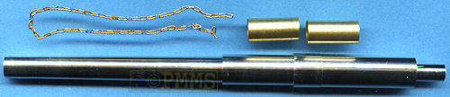
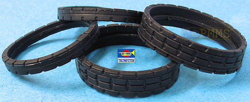
This contains 267 parts in the usual light grey plastic, the 4 tyres in black vinyl, a turned metal barrel, 2 brass tubes and a length of fine chain plus of course the instruction sheet.
Yinyl Tyres
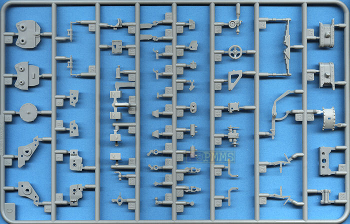
The standard of moulding sees numerous parts having flash to be removed as well as quite a few pin marks and excessive mould seams to contend with. But the details are quite good overall and the thousands of rivet heads around the kit are well done in most cases but there are a few areas where the small mould seam line is between rivets and cleaning this seam off without damaging the rivets will be quite a challenge.
There are also quite a few mating surfaces that have to be trimmed for the parts to fit properly and for mine too many instances where the locating pin or tab would not fit into its corresponding locating hole without trimming; this adds a little frustration to the assembly process.
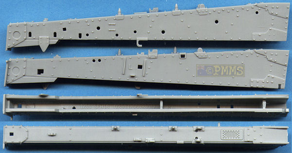
While the kit detail is basically good there are things that need attention along the way and I will step through the instruction assembly sequences to describe the kit and add any comparison comments along the wayThis is not the best start as the carriage has some major issues in that the carriage and main axle are 5mm too wide when comparing to the technical data in the ROSSAgraph s.F.H18 book which puts the carriage profile out and also results in the trail locking device being way oversized. The rivet layout around the carriage is also not correct, most notable at the sides where the rivet pattern on the actual carriage has a distinct kink on the top rivet line with the rivets on the kit carriage being in a straight line.
As mentioned the axle is also 5mm too wide with the spring unit the correct width but it would take major work to correct the carriage and axle widths and the design of the carriage parts means there are join seams around the top and bottom edges that need to be eliminated.
The other issue here is the central trail locking mechanism is way oversized as a result of the extra width of the carriage; this is evident when comparing the parts to available photos of the gun. The two locking levers are also hard to fit as the locating holes are square and the pins on the levers are round bringing up the perennial “round peg in a square hole” and some minor trimming may be needed when fitting these.
The front hand wheel assembly is made up of 6 parts that are a little fiddly to put together requiring some trimming but also includes the tail light sometimes fitted to the carriage.
There are some fine parts here that will need care removing the moulding seams and again some trimming will be needed for the smaller parts to fit neatly and the connecting rod also lacks the small brackets. Other than that assembly should be straightforward following the instructions.
The wheel rims have inner and outer discs with nice bolt head and other details with the central attachment fitting a separate part as is the mounting plate on the inside. The actual tyres are in black moulded vinyl and have the earlier notched tread pattern.
Detail on the vinyl tyres is nicely done but there is a large moulding seam around one side of the tread which will be difficult to remove with the vinyl tyres fairly easy to fit but don’t stretch these too much while fitting for a better fit.
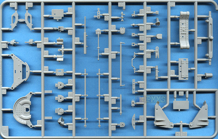
Both the trunnion side panels have nice details although there are some pin marks and moulding seams along the edges to deal with and the Pneumatic Equilibrator mountings on the front of the trunnions are separate small parts so take care you fit these to the correct side?
Fitting the trunnion sides to the base will require some trimming of the mating surfaces as they were quite rough on my parts and added to the middle of the assembly is the long piston that attaches to the underside of the gun cradle.
There is actually a piston cylinder that sticks out the front of the trunnion assembly (quite evident on photos) but Trumpeter have done this wrong as there is just the piston extending out from the base which would move when the gun is elevated. This should actually have the outer cylinder of a larger diameter fitted to the front of the base with the piston going inside and you could use a section of plastic tube to add this cylinder to the kit. Added to this is that the piston doesn’t extend out the front of the base when the barrel is in the neutral position as it would be during travel.
The instructions indicate to glue both trunnion sides to the base in step 7 but this will make it difficult to add the gun cradle later as you will have to force out the trunnion sides quite a bit and I would recommend you only glue one side now and leave the other until you fit the gun cradle in step 14.
Jumping to steps 15 &16 you add the elevation assembly to the left trunnion side and this is quite complicated being made up of 17 separate small parts and there is again a fair bit of cleanup and trimming required to get these to fit together correctly with the instructions being a little vague on exactly where some of the smaller parts should fit.
The main sight is made up of a further 5 parts and the instructions indicate to add these in step 16 but the full sight would not be fitted in the travel mode, just the mountings and as the kit is optimised for the travel mode this should be taken into account.
The gun cradle is in the conventional two halves which results in a join seam down the middle to be eliminated which is all but impossible from the rear section as are the couple of pin marks on the inner sidewalls of the cradle. The rivets on the cradle are rather simplified as there are not enough of them in most places and the width of the cradle is slightly too narrow at the back. The forward upper panel (part D21) forces the front section out wider leaving a noticeable change in width part way along the cradle but this is hidden once the barrel is fitted so should not be a problem?
There should also be a pinion shaft along the rear inner lower left side of the cradle but this is missing and adding this from thin plastic rod or wire would be best.
Added to the sides of the cradle are the two recuperator cylinder supports and the details are quite well done on these but there is no internal detail but this area is mostly hidden when the barrel is in place so is probably not a big deal. One thing to note here is the locating tabs for the two recuperator cylinder supports (parts D50, D51) are a little loose and you should ensure both are aligned perfectly when glued or the top recuperator cylinder will not sit evenly.
The main recuperator cylinder is in two halves but is a good fit leaving just a small seam to be eliminated and the central section with the supports is in two parts with two rear sections and these fit together quite easily. When fitting to the lower.
The thin recuperator cylinder piston that connects to the mounting on top of the breech is not included and if showing the barrel in recoil (such as in travel mode) you will have to add this from thin rod or wire.
The biggest issue here again is the lower gun slide (part E8) that does not have the lower lip that allows the slide to fit over the gun cradle but instead is just flat designed to glue onto the cradle in the firing or recoil position. This missing detail is quite a prominent feature of any gun/howitzer, not just this kit and its absence here is as puzzling. To fix this you need to glue a length a thin plastic strip along the bottom of the gun slide and when dry trim and sand to blend in with the slide.
After adding this strip the slide fits to the cradle which has the upper slide guide as it should and you can easily show the barrel in the firing or recoil position but more importantly the detail is as it should be. Just another minor point is that the rear of the gun cradle is slightly too narrow as noted above and if showing the barrel in recoil the slide does not fit well and easily slips off due the narrow cradle but fits fine in normal position as the front of the cradle is the correct width.
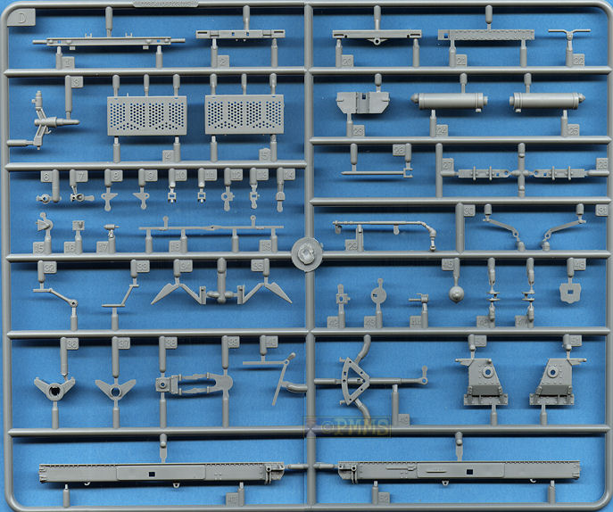
As mentioned you get a new 10.5cm barrel with a choice of two part plastic barrel or a turned metal barrel with both being the correct length and sleeve dimensions, the plastic barrel is fully hollow but has no rifling and the metal barrel is drilled out to a depth of 9mm. There is basic rifling included but this is just a series of over scale straight grooves and again doesn’t look convincing in this calibre.
The breech is made up of three main parts, the breech in two halves and the rear section but the fit was not good and quite a bit of trimming and filling was needed to blend in the rear section (part F5). The breech block has two parts and went together easily but the fit inside the breech is not very good being quite loose and the forward side of the breech block is open meaning you will have to fill this if showing the block open. Added to the top of the breech is the small recuperator piston bracketand the breech block opening handle (part E11) should be in a different position depending if the breech is open or closed but the instructions don’t indicate this.
The barrel has a circular plastic section that fits to the breech which makes fitting the barrel quite easy and most would use the metal barrel to save filling the join seam on the plastic barrel.
This section covers fitting the barrel and then attaching the full barrel assembly to the lower trunnion and base assembly as well as attaching the two large Pneumatic Equilibrators on each side of the gun.
These are made up of the lower plastic piston, the upper brass tube section that fits very snugly over the plastic piston and the top two part plastic cap/attachment bracket. These fit together very easily but the upper join between the plastic cap and the brass tube has to be completely eliminated which can be tricky between the two mediums.
The diameter of the Trumpeter Equilibrators is slightly undersized but we are only talking fractions on millimetres and are probably not worth bothering with.
Fitting the Equilibrators to the trunnion brackets will pose problems as the pins are quite large and almost impossible to fit into the Equilibrators bracket and it would be advisable to fit the two cap parts together around the bracket as you glue them together but this will pose additional issues cleaning up the joins on the Equilibrators, so be warned on this.Both the trail arms are moulding with the top and both sides in one piece due to the use of slide moulds which results in clean well defined rivet and other detail on all three sides as well as being pin mark free. There is a seam line along the top edges of the arms and what seems like a large round pin mark at the ends but both these features are actual details on the real trail arms so don’t be tempted to remove these.
The underside filler plates (parts A25) have a single row of rivets down the middle which is completely incorrect but I guess unless you will be crawling around under the model this will be hard to see.
While the rivets present are represented okay the number of rivets is less than it should be and the size of the forward mounting bracket outline are undersized but most will overlook these issues as there is little you can do without major work and is not that noticeable unless you carry around a reference library.
Most of the details are nicely rendered with separate mounting brackets on some others such as the pioneers tools have moulded on brackets but overall the trails are quite convincing in appearance.
You should watch the main mounting brackets as they look similar but are numbered differently for each arm and depending if they are the top or bottom brackets, so take care not to mix these mounting up during assembly.
It is best to glue one of the top end brackets firmly in place and let to dry completely before attaching the arms as you then only have to worry about fitting the lower bracket during final assembly.
The inner brackets (parts B5, B6) that hold the trails open or closed are also different both sides so watch the numbering and again its best to glue these firmly in place before fitting the arms to the lower carriage. These brackets are undersized as a result of the cradle mounted locking brackets being way oversized as noted in step 2.
Adding the remaining detail parts is quite straightforward but again there was a bit of minor trimming required here and there for a perfect fit but nothing dramatic.
These are again straightforward but watch the position of the four ribs (parts D3 to D6) as they are different and should go as indicated in the instruction diagram but there are a few pin marks on one side of the spades that will need removing. As mentioned there are no indications in the instructions for mounting the spades in the firing position but it should be easy to work out if this mode is chosen?
The limber made up of many small parts and after careful cleanup there shouldn’t be any problems during assembly but take your time as there are a lot of smaller parts and some of the mating surfaces will need attention for the best fit.
The wheels are like the main wheels produced with two part rims with excellent details and the thinner vinyl tyres that again have the notches in the tread pattern and a mould seam around the tread to be removed.
Added to the underside of the limber are the perforated panels that are attached to the trails in the firing position but again this is not shown with just the transport mode illustrated.
Some of the detail on the limber parts is a little on the heavier side but the axles are the correct width.
Steps 30 to 32 Final Assembly
This is fitting of the trail arms to the lower carriage, the gun assembly to the lower carriage, the spades to the trails in the travel position only and attaching the limber.
All is fairly straightforward but there are few things to note, as mentioned the trails are optimised to be in the travel position and the elevation linkage (part D29) that goes from the traverse hand wheel crank on the right trail to the side of the right trunnion is the length for the travel position and would have to be altered if you want to show the gun in firing position.
Also the pin to attach the gun assembly to the lower carriage is not round meaning there is no traverse possible with the assembly again fixed in the neutral travel position and this pin would have to be altered (rounded) to show in any other position.
Finally the chains provided are attached to the limber and trail attachment points.
There are no markings provided in the kit with the colour painting guide showing just one scheme in overall Field Grey.
There is one thing not mentioned in the instructions in that while in the travel mode the barrel is released and stowed in the full recoil position and to depict a gun correctly in travel mode you will need to reposition the barrel accordingly.
As with the sFH18 150mm Howitzer if built on it’s own without referring to any references the kit will build into an okay model of the s.K 18 10.5cm Kanone but has a some dimensional issues.
The kit has excessive pin parks and the lower carriage dimensions and wheel base are a worry but it will look like a s.K 18 10.5cm Kanone if these are not of concern with these issues partly hidden by the wheels. The kit is also optimized towards the travel position with the limber attached as some parts that only fit in travel mode and the trail arm firing position is not even shown in the instructions?
The fact the kit again misses the lower lip on the gun slide is quite bizarre to say the least given this is a major feature of every gun/howitzer but is fairly easy to add.
Recommended 7/10
Click on thumbnails for larger view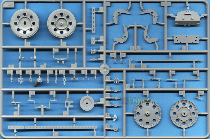
Detail Images
Close new window to return to review
http://svsm.org/gallery/150mm_FH18
http://svsm.org/gallery/150mm_model1918
http://tanksinmoscow.com/Poklon/Foto/sFH18_01.htm
 |
s.F.H.18 |
 |
German Heavy Field Artillery
|
 |
Hummel Sd.Kfz.165 |
 |
Ground Power No.70 |
Thanks to the Australian Trumpeter distributors JB Wholesalers for the review kit.