
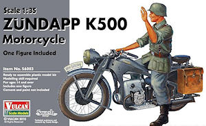
Zündapp K500 Motorcycle w/figure
Vulcan Scale Models 1:35 Kit #56003
Review by Terry Ashley
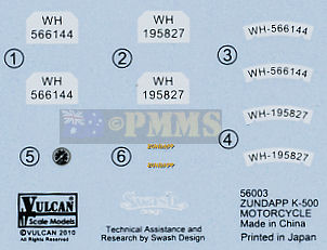
Decal sheet
The kit is quite comprehensive with the major features of the K 500 included and the metal parts adding fine definition while on the other hand there is a number of sizable part location and profile issues that will need some good old fashioned modelling skills to deal with. I have added a few additional details as well as addressing the issues during the kit assembly.
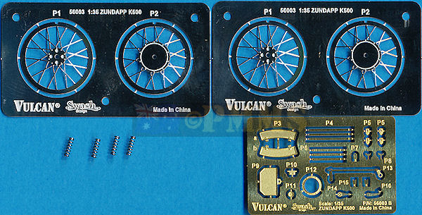
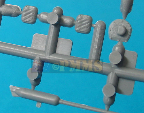
The standard of moulding is quite good but there is a fair bit of fine flash about the place requiring careful cleanup of most parts before use, plus the odd pin mark and the usual moulding seams to be removed with care needed on the small parts included in the kit. The 24 finely etched parts are cleanly done but apart from the front and back number plates are all very small requiring the usual care when handling. The same can be said for the small springs included for the rider and pillion seats, being real springs they must be handled with care, just don’t compress with tweezers or they could quickly go into lower earth orbit.
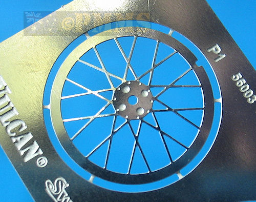
The wheels themselves are the separate disc type made up of 5 disc segments that are sandwiched together trapping the metal spokes centrally in the process. There is some fine flash to be trimmed from around the other edges of some segments and it may be an idea to number the parts with a fine pen as you remove them from the sprues to ensure you fit the segments in the correct order.
When fitting the segments together there is a small amount of play and you have to ensure each segment is located evenly against the previous segment or you could end up with wheels with one tread section offset a little from the others. Also note that the three locating pins on the inside of the outer wheel segment for each wheel are not perfectly symmetrical with two located closer together than the third pin. This is to ensure once all the wheel segments and the spoke discs are joined together the tread blocks and spokes are correctly aligned, so make sure you align the locating pins without trying to force them if not lined up correctly. When they are aligned correctly the fit is good apart from the minor play of the segments as mentioned above.
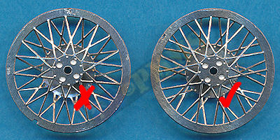
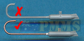
The stainless steel spoke discs are preformed to shape thankfully as it is harder to work with the tougher stainless steel than etched brass so you only have to worry about filing the small bur where the discs are cut from the fret before assembly. Each spoke disc has a small notch that fits over a corresponding locating notch on the outer wheel segments to align the spokes but unfortunately this results in the spokes actually being misaligned.
The spokes ends shouldn't meet at the same spot on the rim but overlap and you will need to remove one (or both) of the small plastic locating notches on the outer wheel segments, I also found it easier to glue the two spoke discs together before fitting into the wheel segments as this made getting them aligned correctly far easier.
I didn't actually notice this until I had assembled the wheels resulting in the images having the wheels with the incorrect spoke alignment, apologies for that.
The image on the right has the correct alignment with the spoke ends overlapping as they should.
The assembled wheels look good and a light sanding of the tread will eliminate any remaining flash or inconsistencies in tread bloke height ready to be fitted as you progress with the assembly.
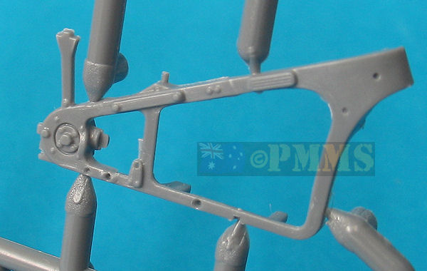
Attached to the central mounting are the two fork frames with the front fender trapped between them, ensure the longest part of the fender is positioned towards the rear. Allow the glue on this assembly to dry completely and then fit the front wheel into place, I had to thin the locating pin on the right fork a little to fit into the hole in the wheel hub but other than that the fit is good allowing the wheel to rotate freely.
Added to the assembly is the rear plastic fender support with two small etched fittings and the two etched forward supports and two part front number plate, it’s best to leave the two part head light off at present as this has to be mounted level with the ground line after the fork assembly is attached to the body later.
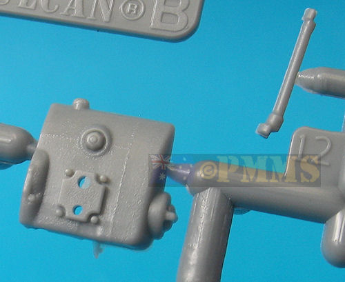
The front profile of the engine is too squared and should be more rounded (see image below) but this is mostly hidden by the bike frame and front wheel forks on the completed model so may not be an issue with some?
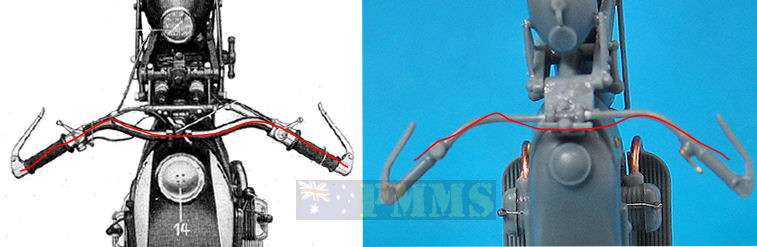
I added the two spark plugs and wire as these seem very conspicuous by their absence to add a little additional detail to the engine block.
Added to the engine is the gear box with separate gear change lever and engine start pedal along with the battery and it is advisable to test fit these as a couple of locating holes needed enlarging slightly for a better fit.
The lower sump (part B6) is added to the bottom of the engine block but this appears to be positioned the wrong way around in the instructions, more on this below.
It may be an idea to leave the foot pegs off until the frame halves are joined as they can easily be damaged during the final frame assembly, other than that there were no other problems encountered.
The final assembly of the frame halves has the assembled engine plus the rear wheel and fender trapped between the frames in the process, the right pin hole in the wheel hub had to be enlarged (drilled) a little to fit the pin on the right frame brake drum. There are two lower edge brackets on the frames that join together and the forward of these fit into the recess in part B6 to secure the engine in place.
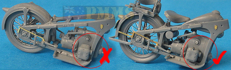
This unfortunately results in the engine being about 1.5 to 2mm too far forward in the frame with the cylinders hard up against the forward frame when they should be the same 1.5 to 2mm further back inside the frame (see images).
It appears the lower sump (part B6) should be fitted the opposite around than that shown in the instructions with the recess to the front of the engine block as this would see the engine set further back. I am assuming this as I had glued the engine in place before noticing the incorrect position requiring some minor surgery to fix.
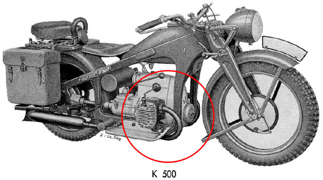
and the corrected position shown against an image from the K 500 Operator's manual (right)
K 500 Operator's manual image showing the correct position of the engine within the frame
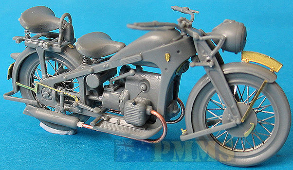
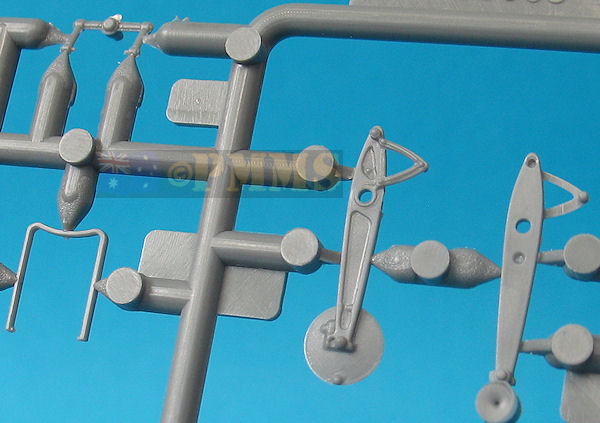
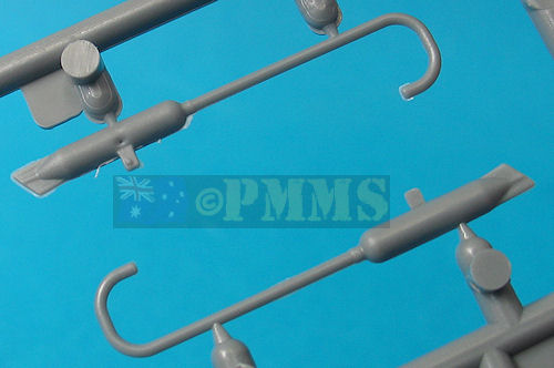
As a consequence of repositioning the engine the rear drive shaft (part B12) and the two exhaust pipes also need to be shortened, the forward bend contours of the two exhaust pipes also have the incorrect profile being too square when they should be a smooth curved profile at the front. To fix both the pipe length and curved profile I replaced the kit pipes with copper wire of the appropriate size.
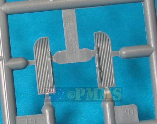
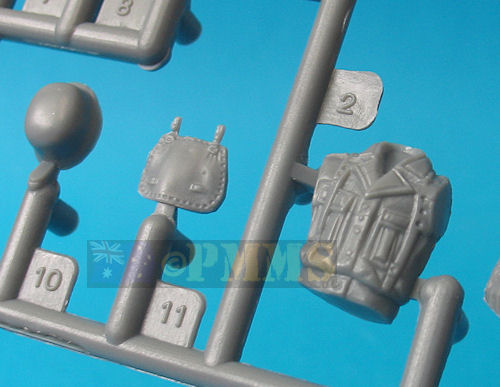
These include the top fuel tank with four parts and the rider’s seat and rear luggage rack with rear pannier seat. Both the seats have the small metal springs for excellent definition and attaching the ends of the springs to the seats with cyanoacrylate will make sure they are not lost while fitting the seats. There are a series of small studs around the back of the seats but after cleaning up the mould seams these weren’t in the best condition and I replaced these with small resin round rivet heads for better definition.
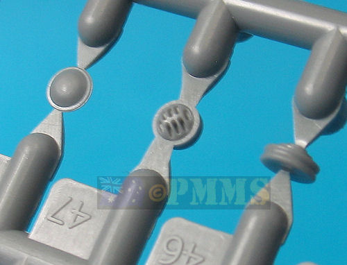
Other items added are the small auxiliary tank, front mounted horn and rear stand in plastic along with numerous small etched fittings plus the rear fender supports and number plate, these etched parts add nice definition to the final model.
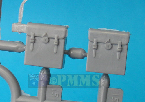
The two rear luggage pouches can be attached to the luggage rack if you wish to fit these to complete the main body assembly.
Lastly the front fork assembly is attached to the body and this required the pin locating holes in the body frames to be enlarged to take the fork locating pins. The upper pin is included with the central fork mounting while the lower attachment bracket (part A21) is attached to the forks, the locating pins on part A21 are way too small for the opening in the forks so you should align these as you glue the bracket to the forks after inserting the pin into the underside of the main frame. Once the forks and frames are assembled you can attach the headlight ensuring this is fitted horizontally to the ground line.
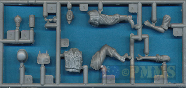
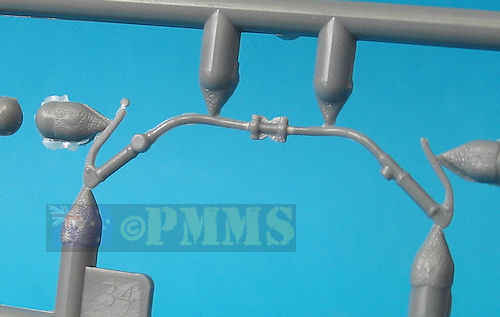
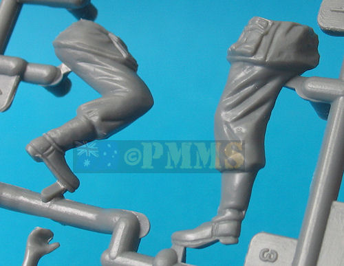
There is also scope to add the additional engine wiring and control cables to the handlebars to finish off and the inclusion of the rider figure is a nice touch.
If you are prepared for some extra work a very nice model of the Zündapp K 500 will result but as said the issues do distract from the build ability of the kit as it comes in the box.
Recommended.Click on thumbnails for larger view
Assembly detail Images
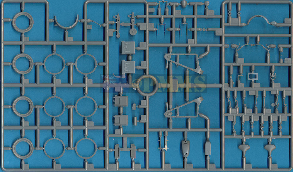
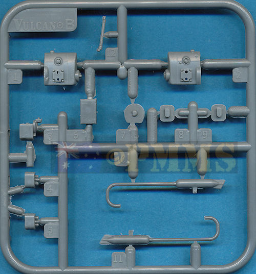
Sprue detail images


Close window to return to review
| Heavy Sidecar Motorcycles of the Wehrmacht 1935-1945 Schiffer Publications ISBN: 0764312723  |
Motocykle Wehrmachtu Tank Power Vol.LXVIII Wydawnictwo Militaria No.300 ISBN: 9788372193001  |
Thanks to Vulcan Scale Models for the review kit.
