
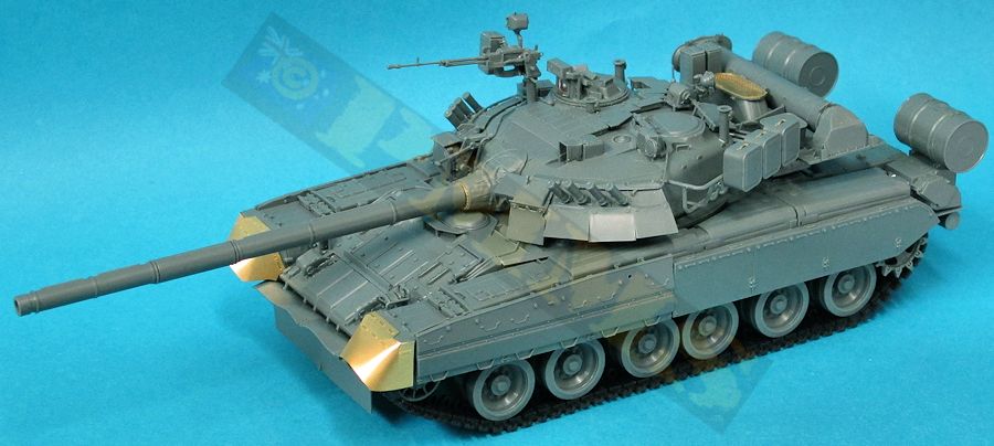
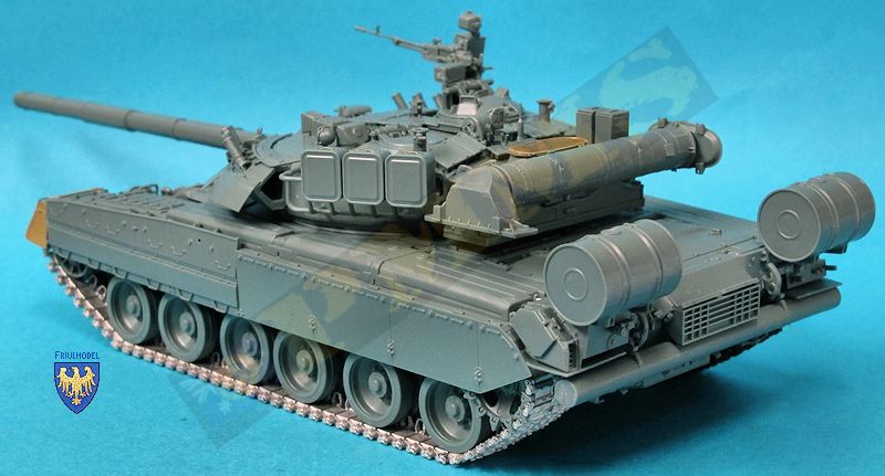
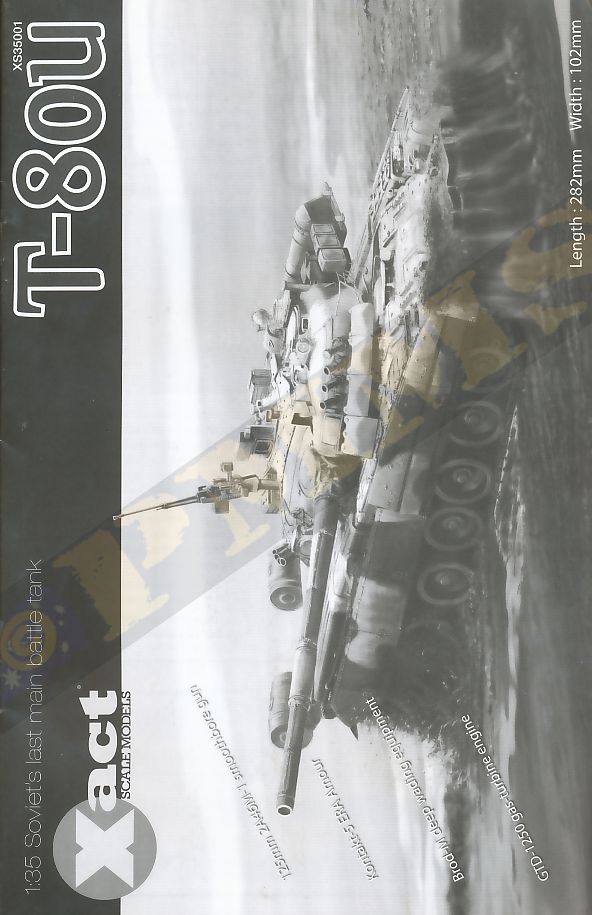
T-80U Russian MBT
Xact Scale Models 1:35 Kit #XS35001
Review by Terry Ashley
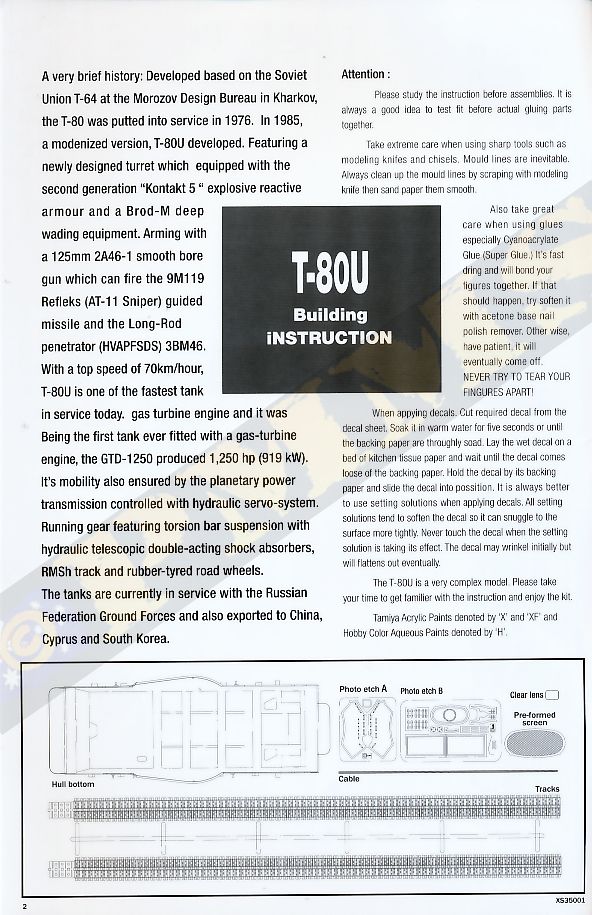
A very brief history: Developed based on the Soviet Union T-64 at the Morozov Design Bureau in Kharkov, the T-80 was putted into service in 1976. In 1985, a modernized version, T-80U developed. Featuring a newly designed turret which equipped with the second generation “Kontakt 5“ explosive reactive armour and a Brod-M deep wading equipment. Arming with a 125mm 2A46-1 smooth bore gun which can fire the 9M119 Refleks (AT-11 Sniper) guided missile and the Long-Rod penetrator (HVAPFSDS) 3BM46.
With a top speed of 70km/hour, T-80U is one of the fastest tank in service today, gas turbine engine and it was Being the first tank ever fitted with a gas-turbine engine, the GTD-1250 produced 1,250 hp (919 kW). Its mobility also ensured by the planetary power transmission controlled with hydraulic servo-system. Running gear featuring torsion bar suspension with hydraulic telescopic double-acting shock absorbers, RMSh track and rubber-tyred road wheels.
The tanks are currently in service with the Russian Federation Ground Forces and also exported to China, Cyprus and South Korea.
The kit consists of:
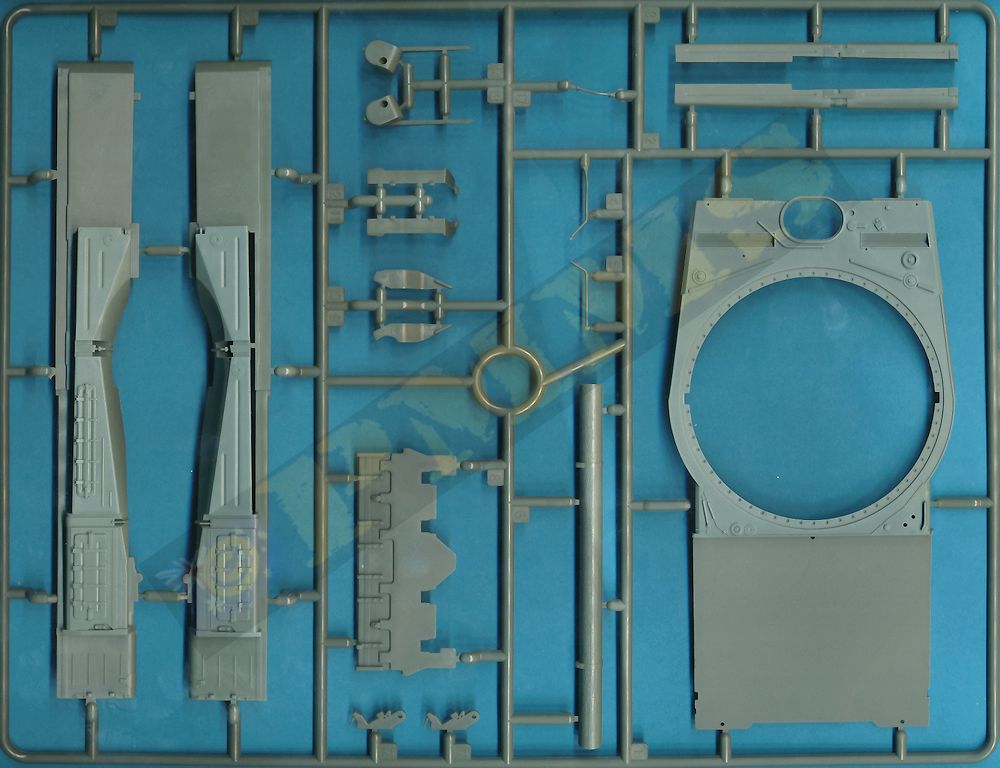
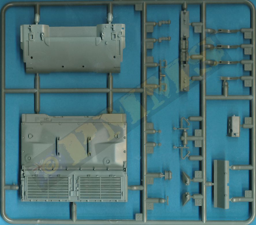
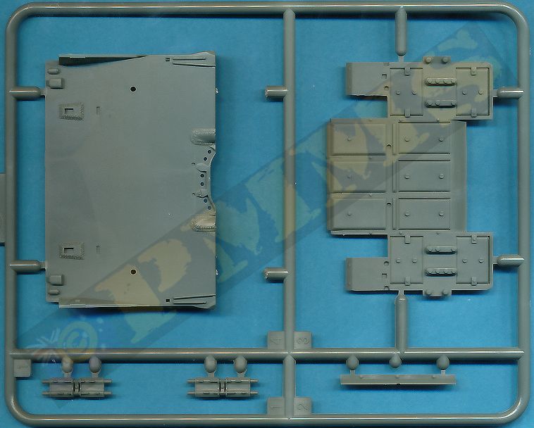
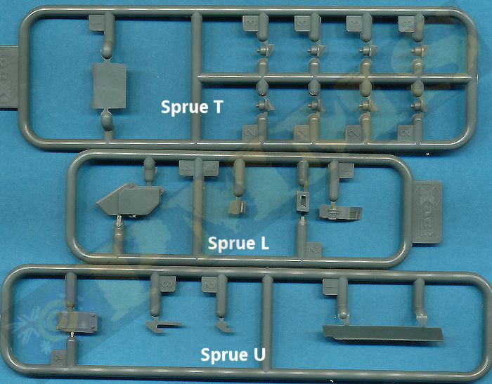
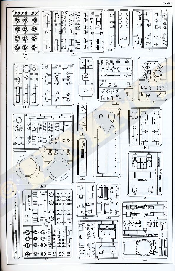
391 parts in dark grey plastic on 24 sprues
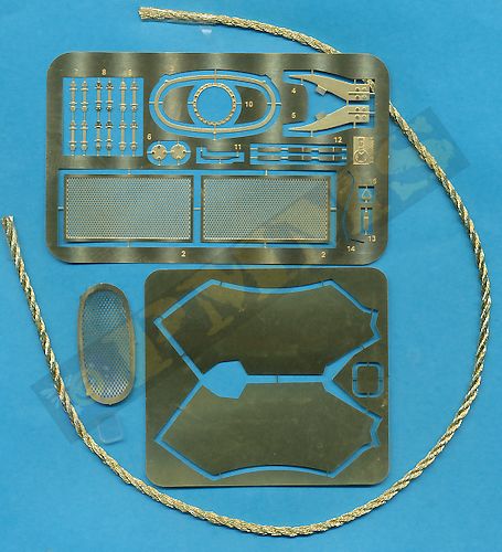
33 Etched brass parts
1 small clear plastic lens
1 length of braded copper wire
1 set of vinyl type full length tracks
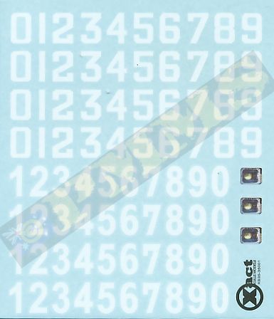
1 small decal sheet
20 page instruction booklet
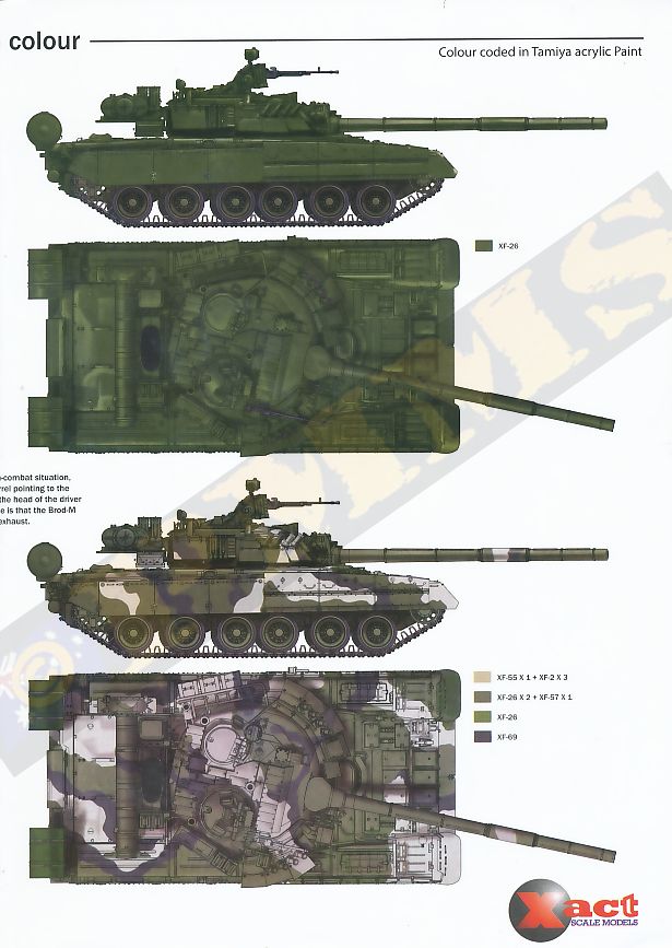
2 page colour painting guide
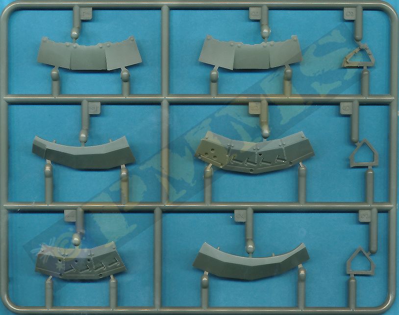
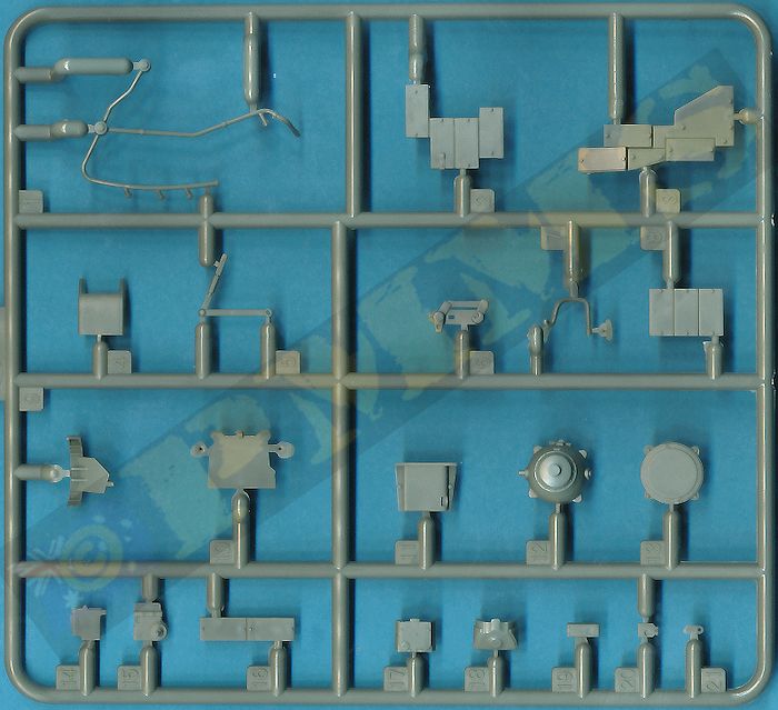
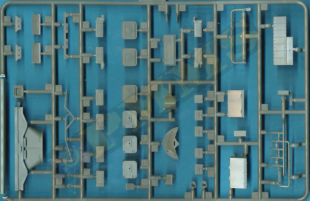
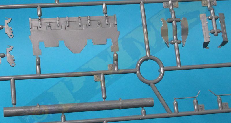
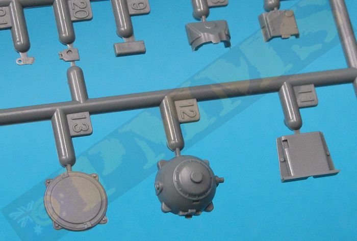
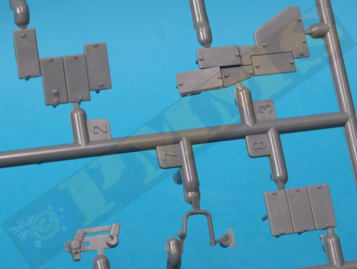
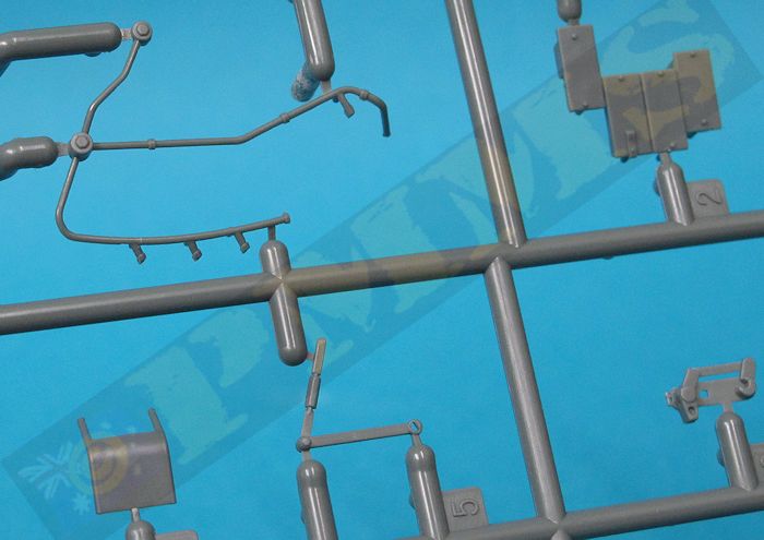
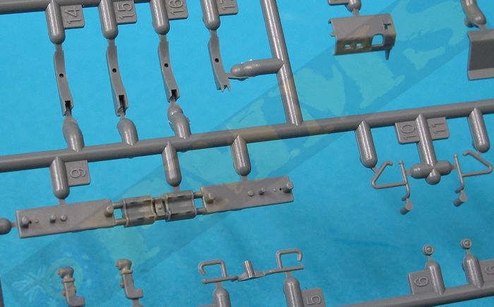
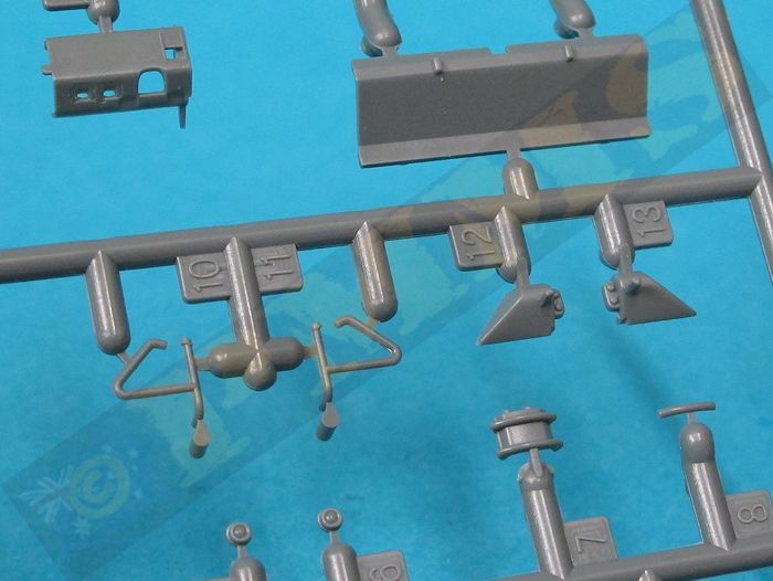
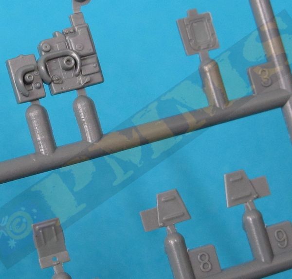
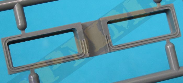
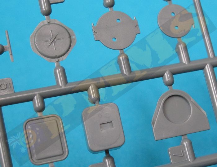
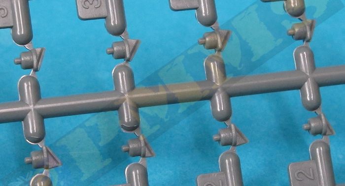
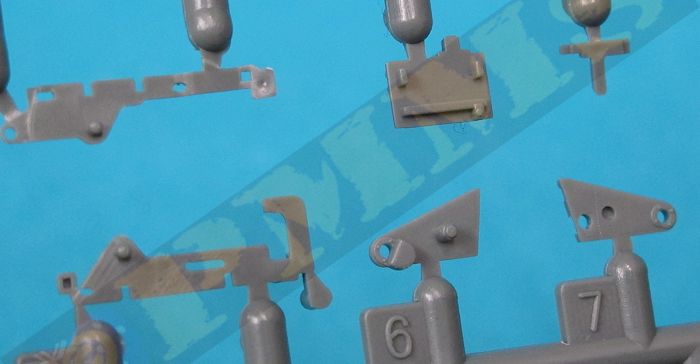
The standard of plastic moulded is excellent with clean crisp detail on the parts and virtually no flash and just the occasional pin mark that will be visible after assembly with just the usual mould lines to be cleaned from the parts prior to assembly. The other noticeable thing is the parts are almost totally devoid of the myriad of plastic nodes we have become used too on contemporary kits these days, these are only present on some on the very small parts and this does make the job of part clean-up a lot easier.
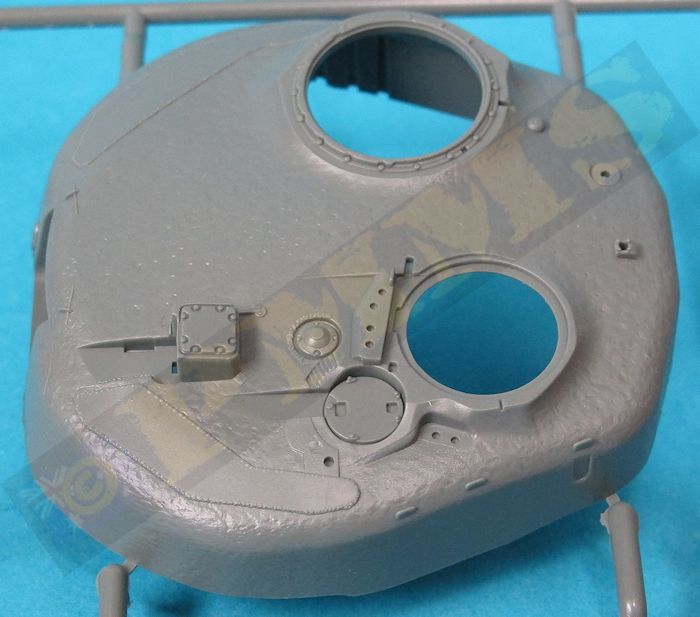
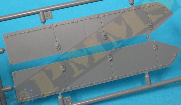
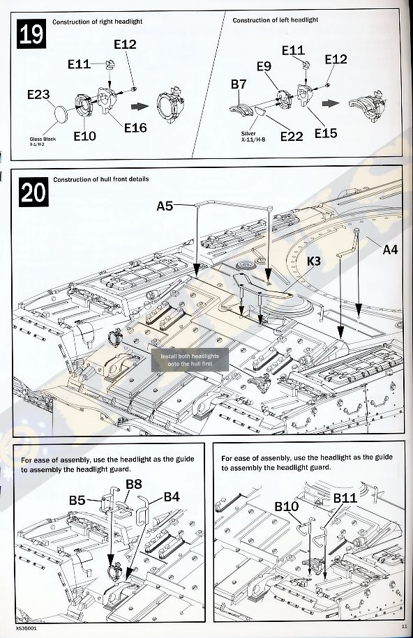
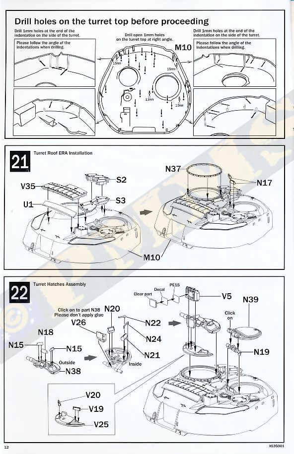
Surface details are very well done with a mix of engraved/recessed details, weld lines, raised detail, bolt and rivet detail including some flush screws and cast texturing on the turret for a good overall appearance. There are some very small parts that need care removing from the sprues and during assembly, none more so than the small clear sight lens. This is a single small clear part that isn’t on a sprue, just loose and measuring just 5mm x 4mm is almost invisible and very easy to lose unless you put it somewhere safe like in a zip lock plastic bag until you need it in step 22.
Dimensionally the kit measures out very well against the 1:35 plans in the Polygon T-80 book and Concord #7503 T-80 book listed below in all areas such as the road wheels, hull and turret sizes as well as the larger individual items such as the engine deck, rear exhaust box, crew hatches, Brod-M wading system, rear fuel drums and fender details, the only part that differed was the barrel dimensions, see below for more details. That is the only area where the kit parts differed from the plans to any degree other than what would be acceptable tolerances for printing etc.
The kit isn’t for the inexperienced modeller as there are some quite intricate assembly sequences and sub-assemblies that will need care and unfortunately the instructions make things a little vague in some instances. These are the usual exploded view drawings and quite busy in places due to the number of parts and while good overall there are a few steps with the turret assembly where it’s difficult to work out where some parts go and careful study of the illustrations along with test fitting will be needed, additional reference material will also be of assistance in fitting some parts, more details are listed below.
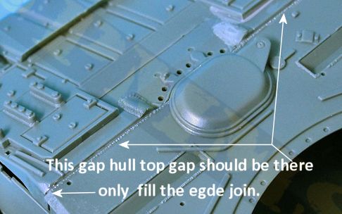
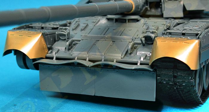
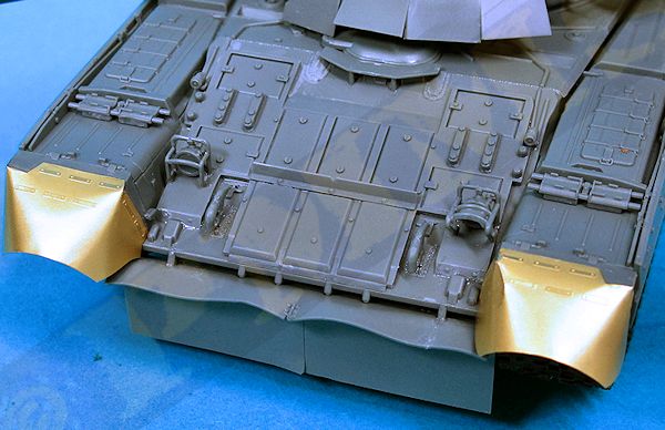
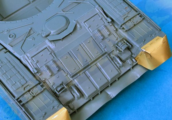
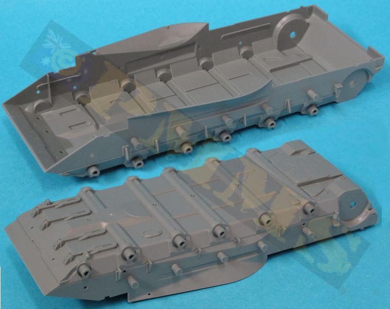
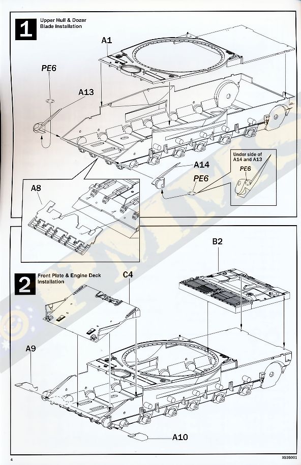
The front scraper blade is added under the front hull and this is moulded closed but is hidden by the front rubber mud fenders after assembly so isn’t an issue, the glacis has separate reactive armour and I found it easier to glue this to the glacis before gluing the glacis to the hull. You should note that after gluing the glacis there is a large slot on the hull sides, this is for fitting the fenders so don’t worry, there are also joins at the sides and the top edge that can be filled but the side gaps are hidden by the fenders so the only gap to be filled is the small angled side section. What appears to be a large gap along the top glacis/hull join should be there, on the real T-80 there is a distinct recess weld along this join and the kit represents this, so don’t be tempted to fill the top join line.
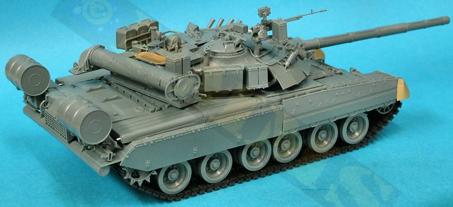
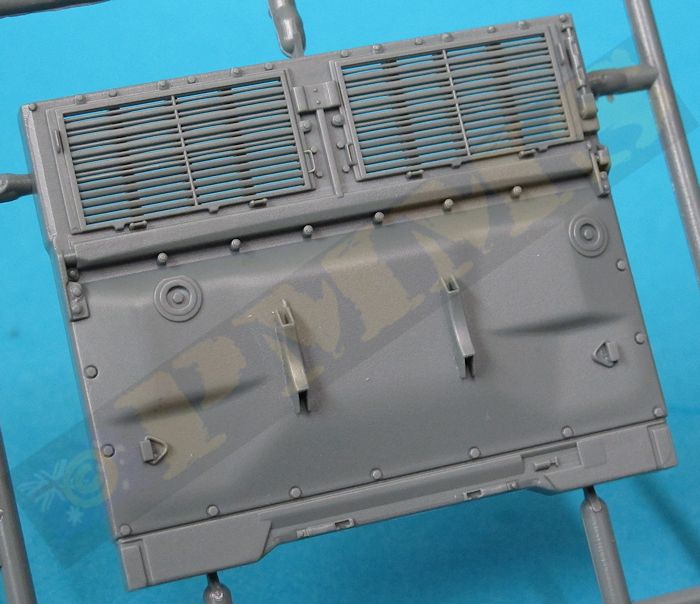
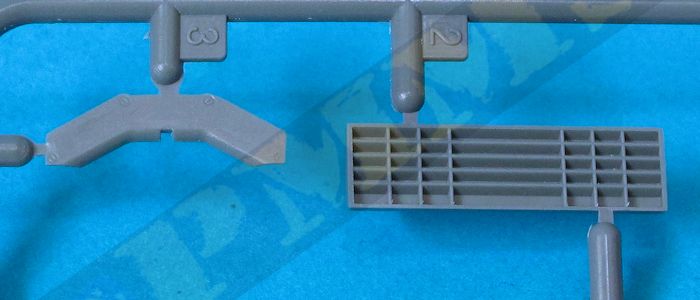
The two idler mountings are also added to the front corners and you should ensure these are aligned perfectly with the hull sides while at the back you glue the separate engine deck to the hull, the fit here is excellent and you don’t need to worry about any side join lines as these will be hidden by the fenders when fitted later. The engine deck has excellent details including raised and engrave detail as well as open intake grills for a nice appearance, the kit includes optional etched mesh for over the intakes but as this a area is very difficult to see on the actual vehicle due to the large Brod-M deep wading equipment the choice is yours to add the mesh if you wish?
The rear hull plate is also added to the hull and this required the side edges be pressed firmly into place while the glue ‘went off’ to prevent gaps and care is needed to make the join as snug as possible. Any resulting gaps along the side joins will mostly be hidden by the fenders and other detail but take care when gluing the rear plate. You should also note that as with the front plate it appears the top join line needing filler but this is correctly depicted in the kit as the actual vehicle has a recessed weld join here, so again don’t be tempted to smooth out this join. D24, ref02
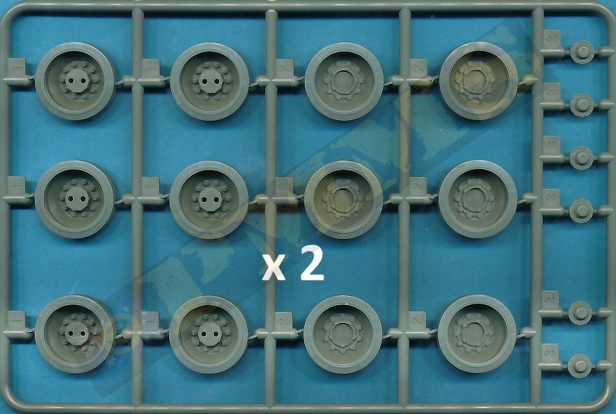
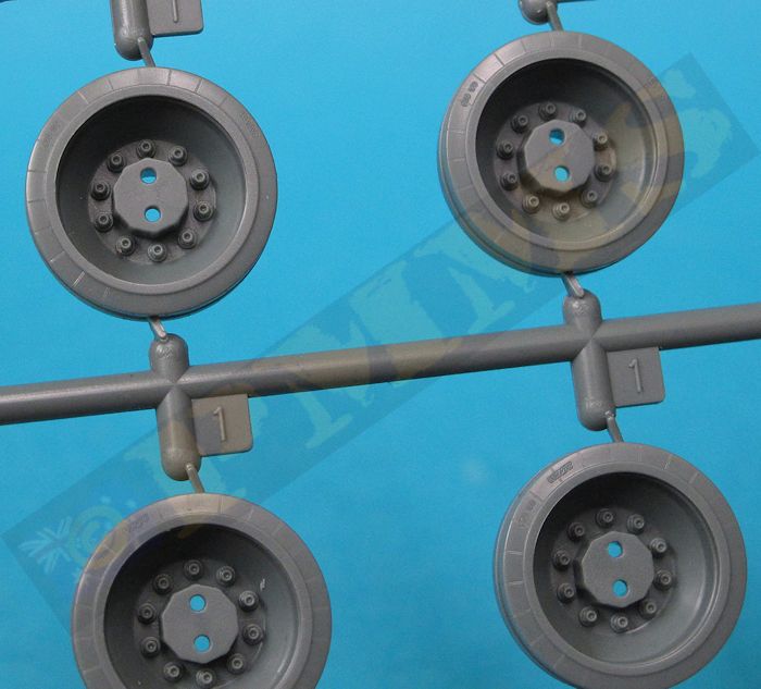
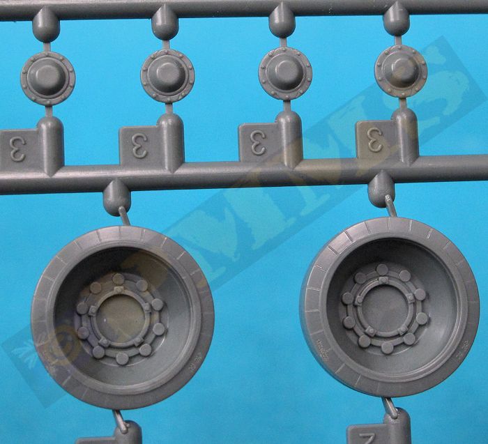
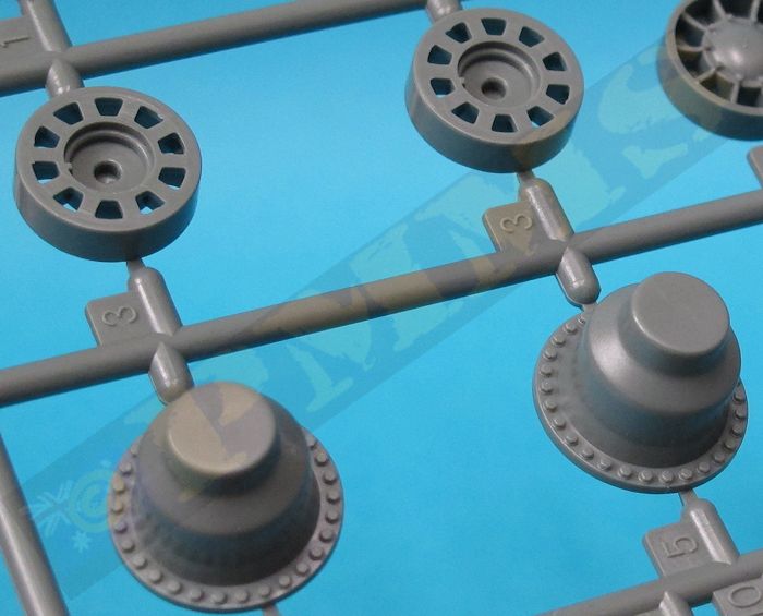
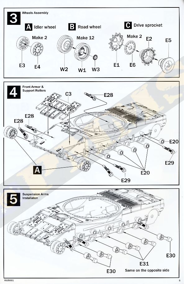
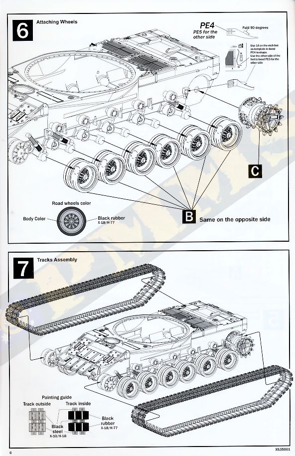
Detail on the idlers, road wheels and drive sprockets is very well done and matches the real things well, idlers are in two parts, the inner and outer wheel and the axle stub fits snugly into the mounting hole and you don’t need to glue these if you want to leave free as they are tight enough to stay in place. The road wheel have the inner and outer wheels with separate hub cap, the wheels have the correct dish profile and nicely represented rim bolts along with the embossing of the tyre segments and data on the sidewalls, there is also the rubber mould line around the centre of the tyre which is present on the actual tyre so you can leave this or remove to show well-worn tyres.
Assembly of the road wheels is very straightforward with the parts just simply gluing together and the axles are glued to the hull mountings by way of large robust mounting points, you just need to ensure the axles are all lever when gluing as there is a little movement possible so check this with a ruler while gluing. The fit of the road wheels to the axles again is very positive with quite large contact area for a strong bond.
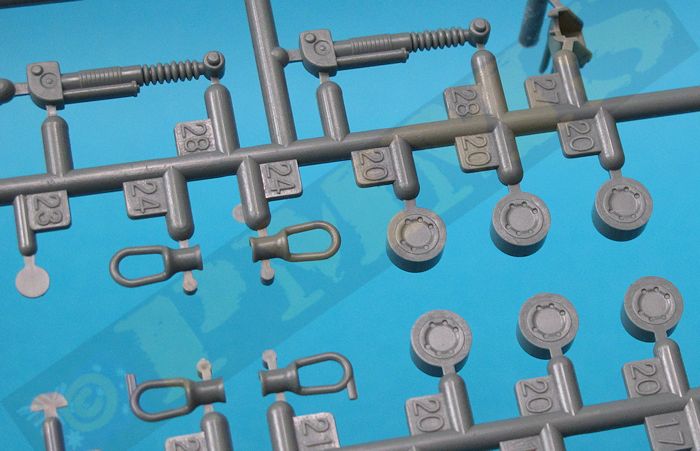
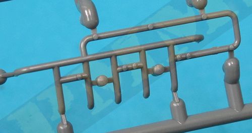
Before fitting the road wheels there are the three shock absorbers (2 front, 1 rear) and these have nice spring detail but the ends are designed to just sit onto the axles without any actual locating holes etc. this isn’t really a problem as this join is hidden behind the road wheels and you just need to make sure the axles are lever before gluing the ends of the shock absorbers to the axles.
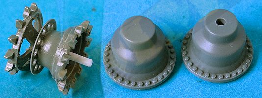
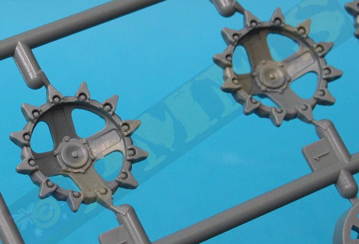
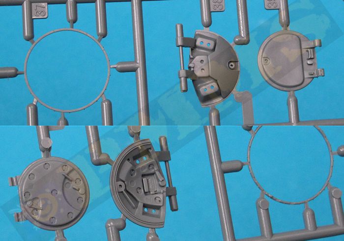
The drive sprockets are also nicely detailed with the spoke outer sprocket with good definition on the outer bolts along with the central perforated disc and the correctly shaped inner solid sprocket disc, the final drive housings are also correctly shaped with the sprockets as mentioned just glued together and the sprocket then glued to the final drive housing not allowing any movement.
I modified the kit drive sprockets by adding a 2mm plastic rod pin to the outer sprocket and drilling a corresponding hole into the final drive housing to allow the sprockets to rotate and also to allow these to be removed and added at any time to aid with the track fitting.
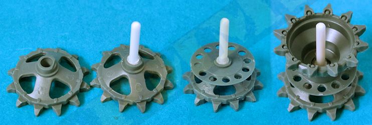
Assembled Drive Sprocket and original and modified Final Drive Housing
There is an etched mud scraper bar for the drive sprockets and this needs to be bent to shape before fitting, the etched fret has a “template” for the correct angles on the scraper but you need to bend the scraper to the right shape before it can fit into the template so sort of defeats the purpose as you can’t actually use the template to bend the scraper but just use this as a guide to the bends. Once bent you can then fit in into the template to check it’s the right shape with the scraper glued in place with cyanoacrylate but not until the sprockets have been fitted, if you want to remove the sprockets at any stage best to leave off the scraper till last as it prevents the sprocket being removed when in place.
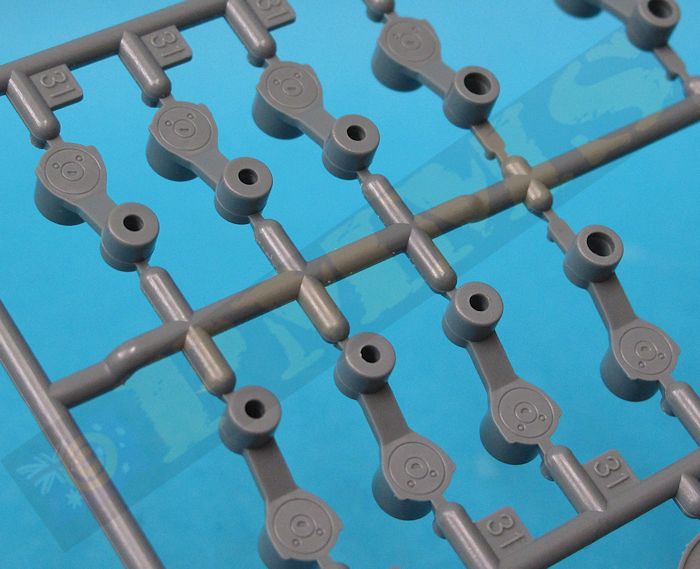
The five return rollers are added to large locating axles but as these are totally hidden after the fenders are added in any case.
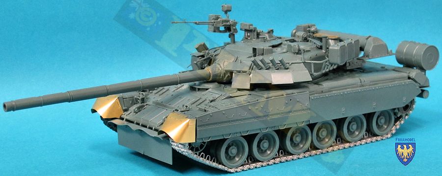
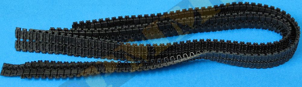
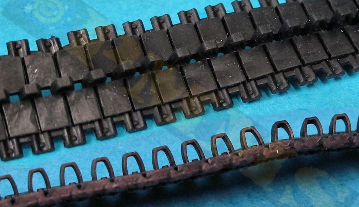
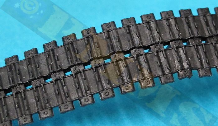
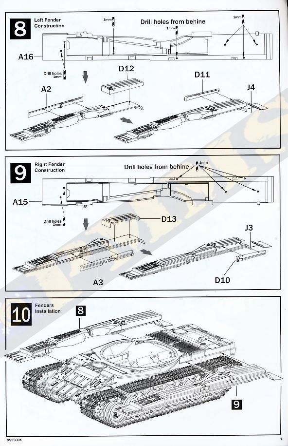
The tracks are one piece full length vinyl type tracks with very good detail for the medium on both the link detail and the fully hollowed out guide horns which do look impressive for vinyl. The only issue was that about every 15th end pin was quite noticeably distorted on my tracks but as this in on one side only this side can be positioned against the hull to hide the distortions. The track ends glue together using normal plastic cement and fit perfectly to the sprockets and are tight enough for the correct sit around the road wheels and idlers, these tracks are well done for vinyl apart from the distortions but lack the gap between each link if you want to get picky and some may wish to replace the kit tracks with aftermarket individual link track (see review here of the Friulmodel set ATL-129 T-80 steel track).
There are two small brackets (parts D2) added to the rear of the fender storage box but these should have a small pin included as shown in the instruction illustration but the pin is missing from the bracket and you can add this from thin plastic rod.
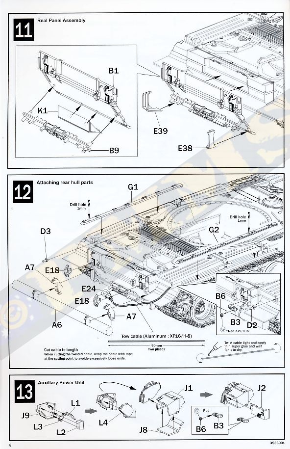
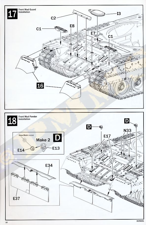
At the front are the separate mud flaps with a small plastic mounting and the mud flaps in etched brass that need to be bent to shape as you fit these to the mountings and I would advise to anneal the brass flaps by running through a candle flame or similar to make the brass softer to bend easier. As it was I found it wasn’t easy to get the bends done as the top corners are sharp bends and the others smooth curves and some manipulation of the brass flaps will be needed. While doing this you need to firmly clamp the top mounting join or this will come loose while bending the flaps to shape, in the end the front profile on my flaps is too rounded according to reference photos. The assembled mud flaps should be left separate until after you have attached the fenders permanently to the hull sides.
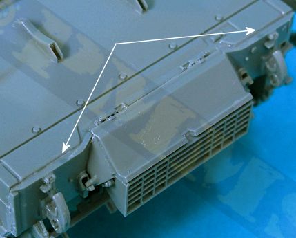
Added to the rear hull are the two side brackets (parts E38, E39), these fit into indentations on the lower rear hull and the small notches higher on the side plate and you do need to be careful as the instructions don’t indicate where the top of the brackets go but it should become apparent when test fitting. You also need to have the rear plate glued to the hull before you fit the brackets and not at the same time as in the instructions.
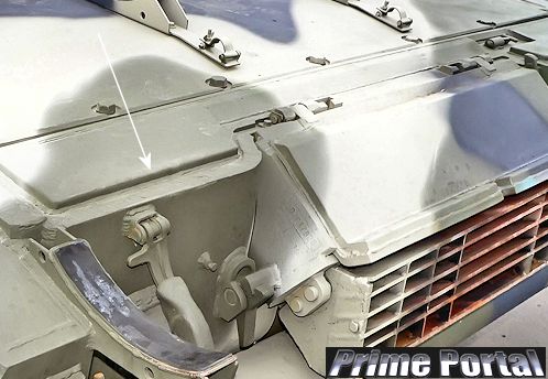
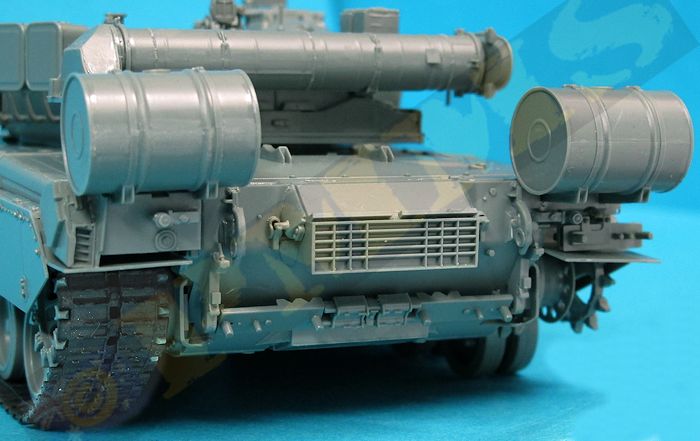
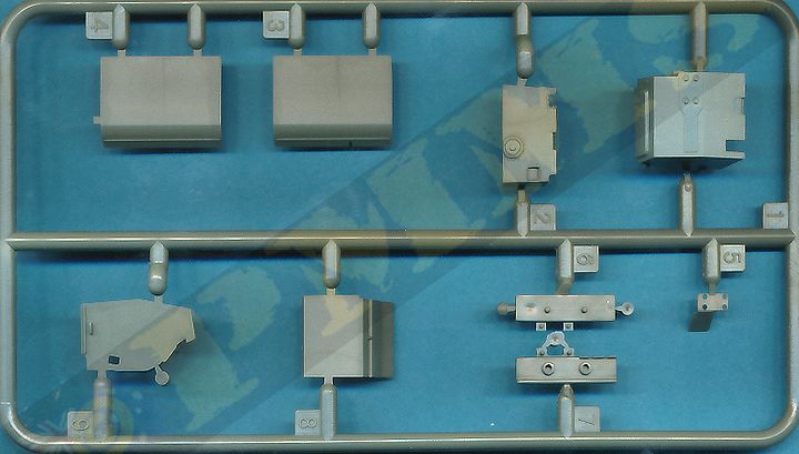
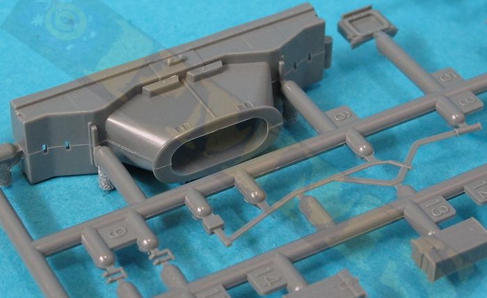
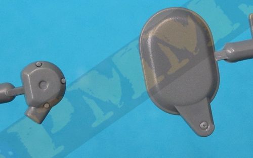
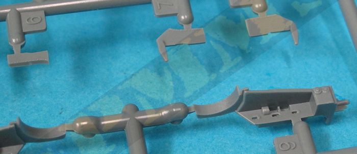
The large central exhaust box has four parts with nice details included although the indentations inside the exhaust louvers aren’t that deep but careful painting should give the appropriate impression, it’s best to attach the side panels (parts B12, B13) to the top panel B19 before fitting these to the louvered box K2 to get the proper alignment of the parts with the assembled box fitting snugly to the rear plate without any problems.
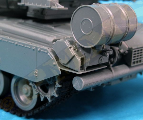
The lower panel K1 and cross member B9 fit easily into place as do the tow hooks, tail lights and mountings for the ditching beam to the rear hull. Assembling the right side parts B18, J5, J6, J7 requires a little care as some of the locating points are a little vague with the assembly only joining to the hull side by the small pin on the side of B18 so you need to make sure the assembly is aligned squarely as the glue dries. You also need to let the glue on this assembly dry completely before fitting the right side fuel tank and one of the tank mounting brackets fits onto the rear hull and the other onto part B18 so you don’t want this to be still moving about while you’re trying to fit the fuel tanks.
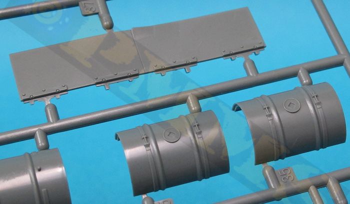
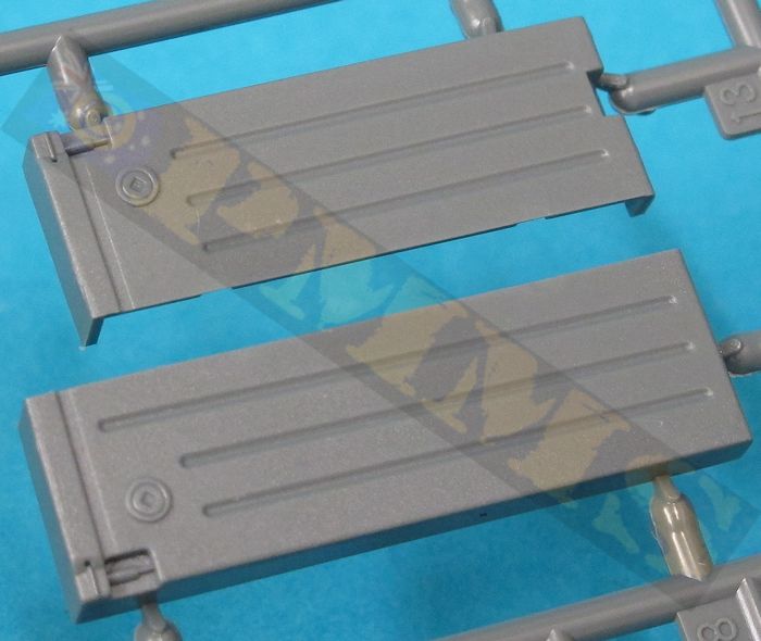
The APU is made up of eight parts that fit together without any problems although you need to take care as you go to get things aligned correctly and each of the two fuel tanks is made up of four parts that again fit together without any problems. The joins on the tanks will need to be eliminated and you need to take note of the four mounting brackets as all are numbered differently and the instruction illustrations in step 15 are a little confusing here. The tanks and brackets are shown facing away from the rear hull and shows the bracket B15 (for example) on the inside but when you turn the tank around to face the rear hull B15 is on the outside, the same goes for the other three brackets so take care.
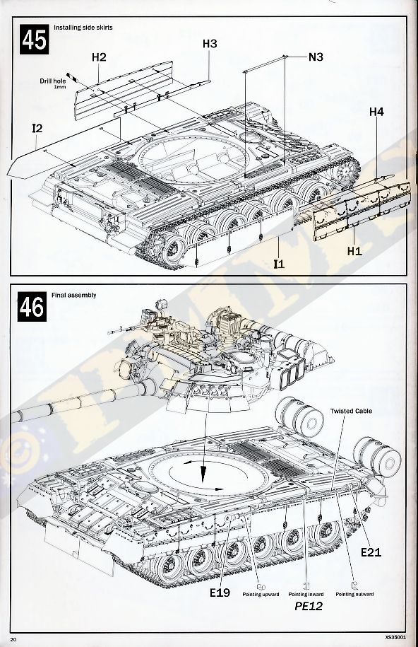
The final item is the tow cables supplied as metal cable which needs to be cut to length and the end shackles added with the instructions giving good tips on handling the metal cable, there are also small etched brackets to add along the hull sides to hold the cables in place.
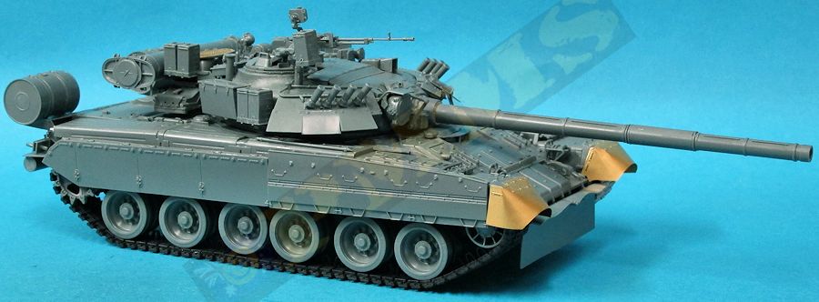
Overall the fit of all the suspension and hull parts was very good with the only filler required being the small side glacis gaps, everything else was trouble free for a relatively quick and easy build given the number of parts and detail included before moving to the turret where most of the action happens.
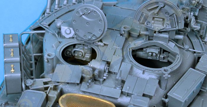
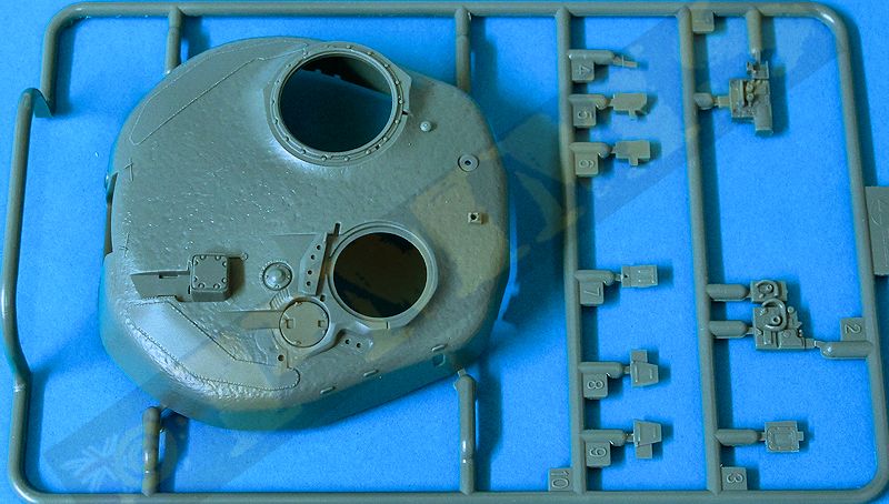
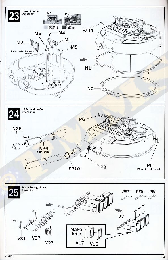
Added inside the turret shell are the Commander’s and Gunner’s sight panel that can be seen if you display the hatched open and of course these would be painted before fitting the two part lower turret ring to the main turret shell.
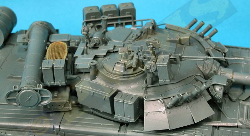
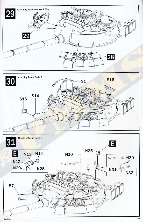
There are numerous sub-assemblies that can be put together separate and brought together for the final turret assembly, these include the two “Kontakt 5“reactive armour packages on each turret cheeks, the large storage rack and ammo boxes, the Commander’s hatch, front mounted search light assembly, the Kord MG and the rear mounted Brod-M deep wading equipment. This allows you to be working on one while the glue on another dries making for quicker assembly.
As mentioned above the main issue here is with the instructions which have every turret illustration from the same left front quarter which makes fitting parts on the back and right side a little tricky at times to get the correct position and you really need care and reference images will help at times to get things right.
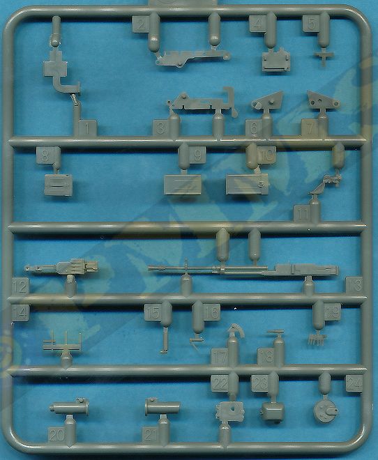
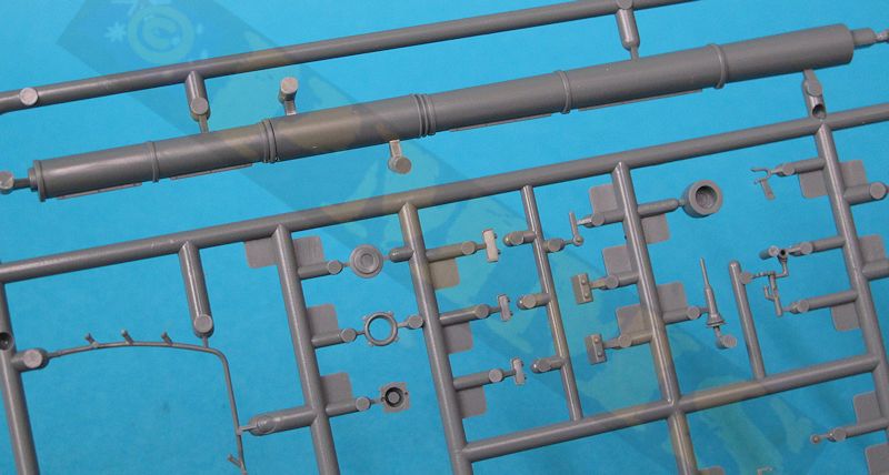
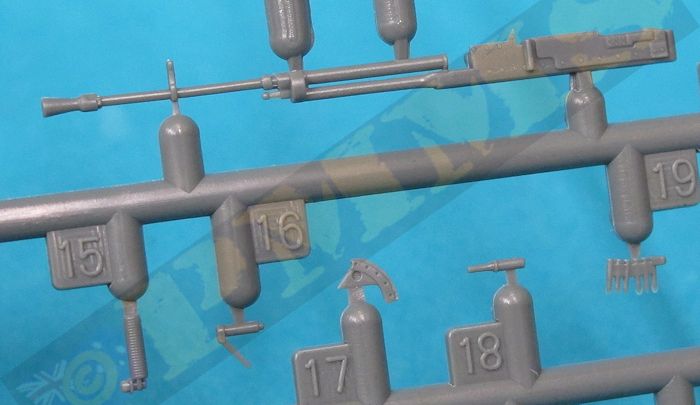
The main gun tube with thermal jacket is moulded in one piece apart from the separate muzzle cap with just a small mould line to be sanded smooth, the muzzle only has a shallow recess which is quite noticeable on such a large bore barrel and drilling this out further will improve the appearance. The inside 3.5mm diameter of the muzzle is the exact 125mm in scale but the length was about 1mm short, not a big deal but the main issue was the lengths between the thermal jackets segments and the position of the fume extractor which differed from that shown in the plans. Both the plans concurred on the barrel dimensions but as a consequence of the different segment lengths the kit barrel had the fume extractor some 5mm further forward on the barrel tube than that shown in the plans.
We are assuming here the plans are correct? Could well be the kit is right and the plans are wrong and without a real barrel to measure I can't say for sure?
The overall length is only 1mm short but the segments differ in dimensions as does the position of the fume extractor.
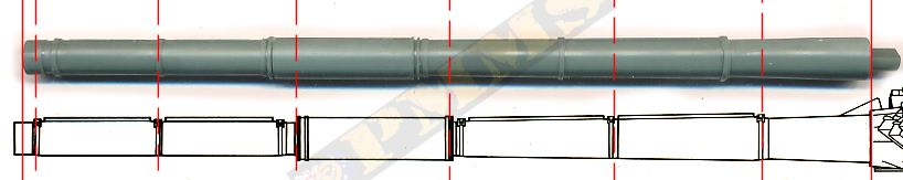
With only 1mm difference in barrel length over a barrel measuring 130mm long in scale isn’t a big deal and it’s up to the individual if the segment sizes are an issue?
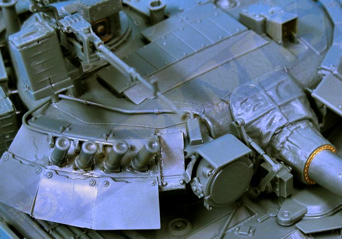
The mantlet has nice texture on the canvas cover and there is an etched bolt ring fitted between the mantlet and barrel tube with the mantlet designed to just glue into the recess at the front of the turret not allowing for any barrel elevation. The turret roof ERA panels fit into the drilled holes but the two smaller rear panels (S2, S16) need care to get in the right position as it’s not clear in the instructions and reference photos will help to get these sitting correctly on the roof.
The Commander’s hatch has excellent detail on both sides of the opening half as well as very detailed main sight with a decal for the optics as well as a total of seven separate periscopes on the inside and outside plus a grab handle and latch on the inside and is quite a detailed sub-assembly but there are few things to watch with the assembly. The large hinge on the opening hatch half is attached to the fixed half by way of part V26 but the angle on the bottom of this needed trimming a little at the right rear corner to sit at the right angle correctly and test fitting will be the best option with this. Also there is a fair bit of movement between the hinge and part V26 and it’s best to temporarily fit the hatches to the turret hatch ring in the closed position as you glue part V26 into place and keep both hatches this way until the glue has dried completely to ensure the two hatches align correctly.
The main sight have a small etched back plate with decal for the optics and front clear ‘lens’ for a good appearance and this attaches to the front of part V26. There is also a two part assembly (parts V33, V36) added over the main sight but the underside of the top section of part V36 needed trimming to fit at the right angle over the top of the main sight to complete what is a fairly intricate sub-assembly and you can attach the hatch inside the hatch ring at any time as the fit is quite snug and will hold in place without glue if you wish.
The large side storage rack and three ammo boxes assembled without any problems and there are etched handles supplied for the ammo boxes to add a little more detail, the rack fit into the pre-drilled holes in the left side of the turret but before adding the rack there is a small weapon pedestal (part E27) that has to be added to the rear left corner, I found the location of this a little tricky and had to refer to reference photos to get the positioning right.
On the right side are the large storage box and two ammo containers with nice details and again the assembly and fit to the turret was good, although the lower drilled hole for the ammo boxes was not quite in the right place due to the angle the hole when drilled and I just altered the pin position for the boxes to sit correctly.
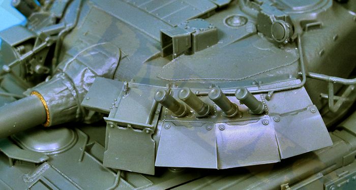
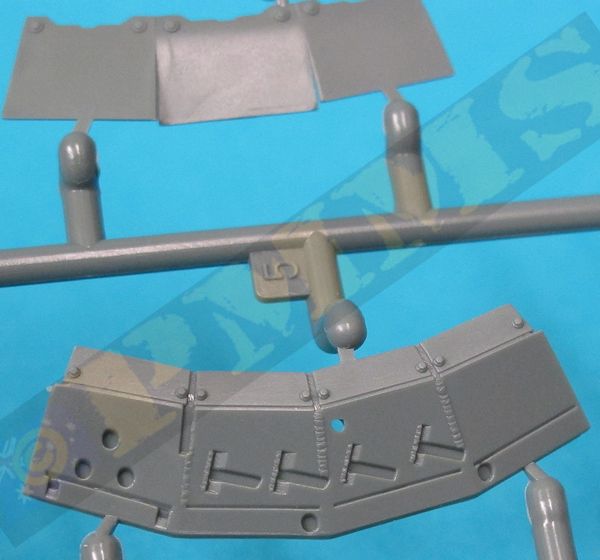
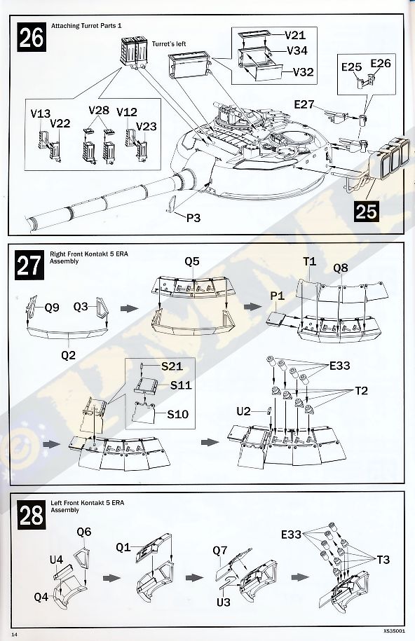
On each cheek are the two large Kontakt 5 ERA sub-assemblies and again the detail is very well done with separate part for the lower ‘flap’ sections for good definition. Assembly was good overall apart from the fit of the top ERA block (parts Q1, Q5 respectively) to the outer brackets and a little care is needed to fit these without small side gaps.
Added to the ERA are the four two part smoke tubes but these did not line up correctly when fitted into the T slots in the ERA panels, the four tubes should be evenly spaced and parallel with each other but were at different angles if fitted as they come. After gluing and letting the glue ‘go off’ I repositioned the tubes so they were at the correct angles, this did result in the bases of a few not sitting snugly into their locating slots but the alignment of the tubes is the main consideration.
Also supplied is the large electrical ducting piping on the turret roof leading to the smoke tubes but you will need to add the final finer wires from the piping to the base of the smoke tubes yourself to finish off the assemblies. The Kontakt 5 ERA sub-assemblies fitted neatly to the pre-drilled holes in the turret sides and should be left for the glue to dry completely before handling.
The large front searchlight is a fairly intricate sub-assembly and care is needed during assembly in particular to get the top curved bracket (part S9) to sit at the correct angle as it is not clear at all in the instructions where the right side of this bracket should fit so I made sure the curved bracket was seated correctly and then added the small part S20 to match the end of the curved bracket.
The searchlight assembly fits to the pre-drilled hole and you must ensure it sits at the correct angle as there is some movement possible with just the single joining pin. A two part junction box (parts S14, S15) is added but again due to the angle of the instruction illustration the location of this is not clear at all and it should fit to the small notch on the side of the canvas mantlet cover.
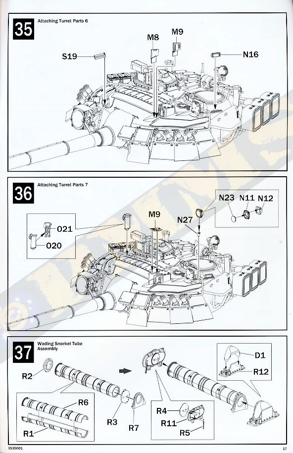
Before fitting the link arm (part S5) you should fit the co-axial MG muzzle and this is solid and will need to be drilled out for a better appearance and there is also an additional electrical ducting added between the turret ducting and the junction box on the mantlet as well as the top cover (S19) and care is needed with this sub-assembly but the end result is quite a detailed and intricate assembly.
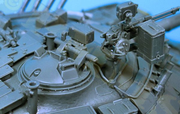
Smaller details added to the turret include the four two part weapons pedestals and you must ensure the larger pedestals located on the upper turret edges are set correctly vertical as the want to lean over due to the angle of the turret curve and the round locating pin on the bottom of the pedestals. Other items such as the small lights and gunner’s sight all fit without any problems and add to the very busy appearance of the turret details. Just one point to watch, the top cover for the gunner’s sight is marked part M9 but in fact should be part M7, this was the only part I found miss-numbered in the instructions.
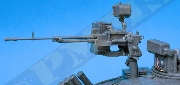
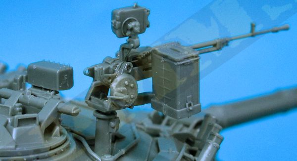
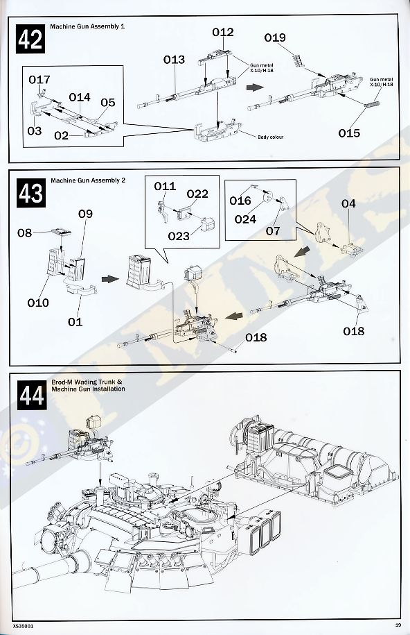
The Kord 12.7mm Heavy Machine Gun is a very nice moulding with just the top cover as a separate part and care is needed eliminating the mould lines especially on the thin barrel, the muzzle is again moulded solid and should be drilled out for a better appearance. Assembly of the cradle will need care due to the small parts but is nicely detailed along with the trunnion mounting and three part Collimator AA sighting gear (parts O11, O22, O23), the location of the arm (part O11) is again not clear at all due to the orientation of the instruction illustration and this arm should fit to the very small notch on top of the right trunnion (part O7). The large four part ammo box fits to the notch on the front of the trunnion base and care is needed to sit the box at the correct angle.
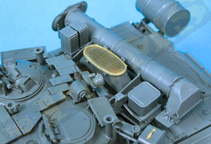
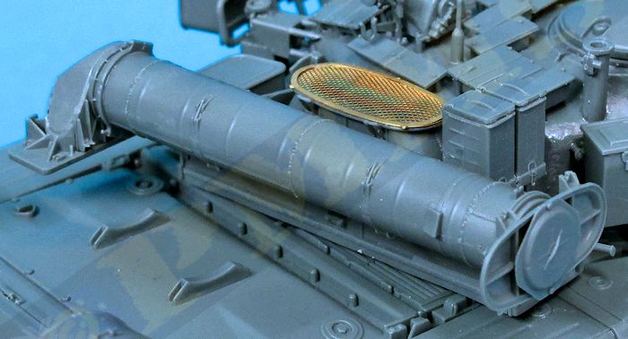
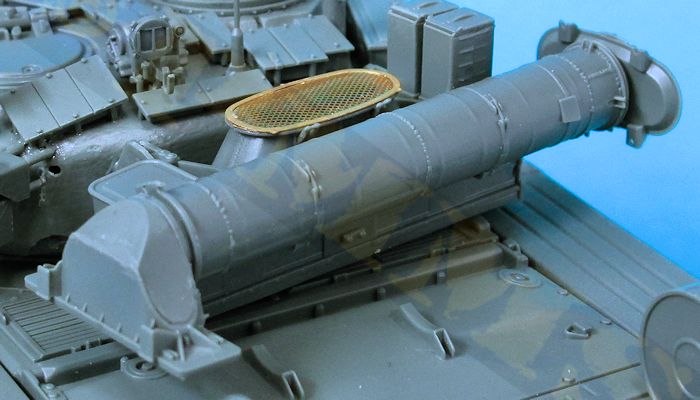
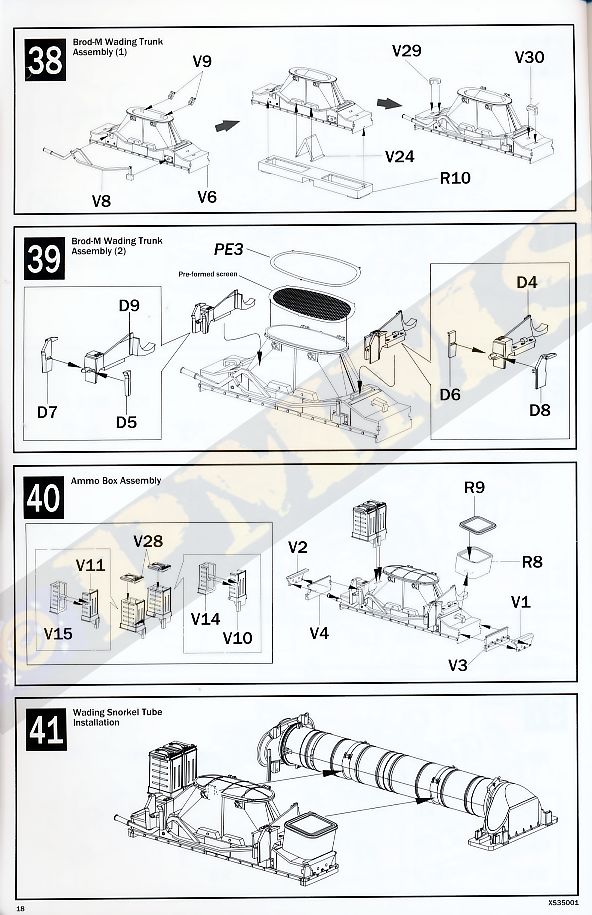
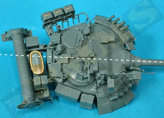
The ammo boxes and other details added to the truck fit without any problems as does the snorkel tube to the wading trunk for an impressive sub-assembly, but note the trunk is designed in the raised travel configuration and if you wished to show this is use a fair bit of modification would be needed to the parts.
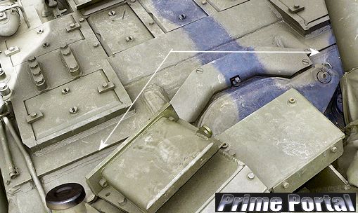
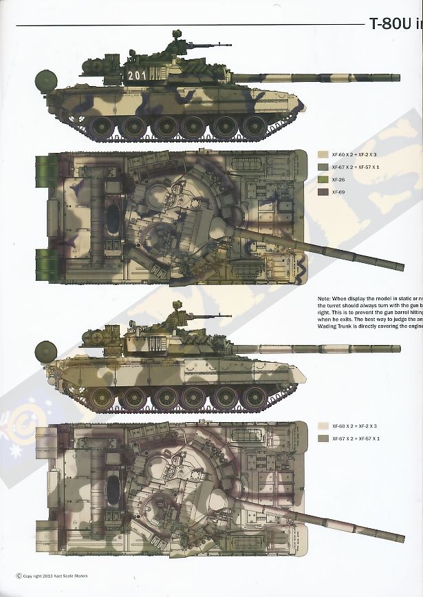
The biggest problem with the wading equipment is not the assembly but the fitting to the back of the turret, as mentioned the instruction illustrations are all from the front quarter and there are just arrows pointing to somewhere on the back of the turret for locating the wading assembly. Added to this the illustrations in step 44 and 46 show the wading equipment mounted at right angles to the turret centre line and this led me to initially fit the wading equipment incorrectly onto the turret. It wasn’t until reading a small note in the painting instructions and referring to additional references did it become clear that in fact the wading equipment should be mounted at an angle on the rear of the turret, this is so the rectangular fairing fits over the engine deck intake grills when the turret it traversed slightly to the right. This wasn’t helped either with the plans in the Concord book incorrectly showing the wading equipment mounted at right angles to the turret centre line which to the uneducated is the logical position. See image here for the correct angle of the wading equipment on the rear turret.
With all of the additional equipment added to the turret it is quite an impressive assembly on its own and this is held in place on the hull by way of the small notches so it can be rotated and won’t come adrift while handling the model.
The fit of the parts is also very good overall with just some minor fit issues here and there and while the kit isn’t for the inexperienced modeller it doesn’t have any working parts such as suspension that can lead to complications on some kits, the only movable part after assembly is the turret travers. As mentioned above if you plan on using aftermarket tracks modifying the drive sprockets to rotate would be an advantage but if not can be left glued in place as they come.
The main issue with the kit is the instructions which are a little vague in mostly the turret assembly due to all the illustrations being from the same front quarter and mixing this up with some views from the opposite side showing the location of the other parts such as the wading equipment would make things earsier.
But all up this will build into an impressive kit of the T-80U and surpasses any other T-80 kit released by a long shot and as with any kit there is scope for adding additional details to enhance the level of detail even further and we can expect the already announced T-84 from Xact Models to be the same standard as this kit which will please modern armour fans.
Rating 8.75/10
Click on thumbnails for larger view
Detail images


Click on thumbnails for larger view
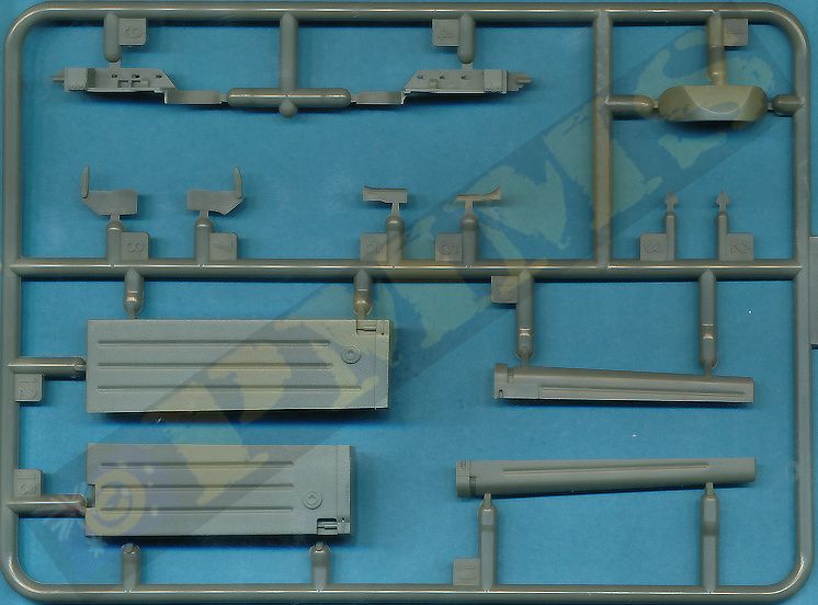
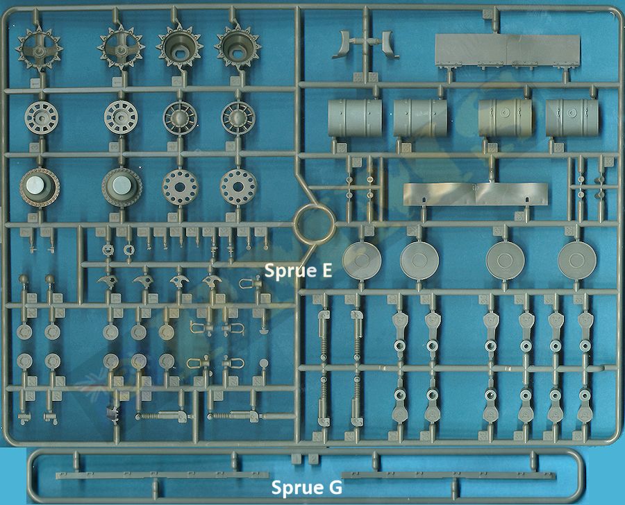
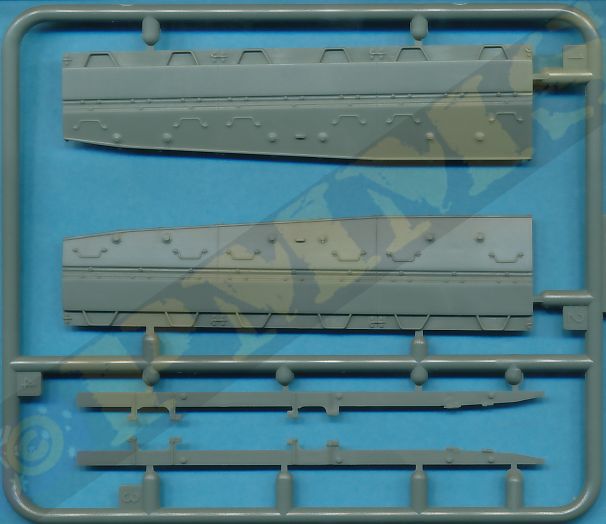


Sprue detail images


Instruction sheets


Close window to return to review
| Main Battle Tank T-80 Polygon Publishing ISBN: 5-88541-006-2  |
Russia's MBT T-80U Concord Publishing 7503 ISBN: 962-361-656-2  |
Ground
Power Magazine #112 - 9/2003 GALILEO Publishing Co.,Ltd.  |
T-64 and T-80 Concord Publishing 1031 ISBN: 962-361-031-9  |
 for the review kits.