

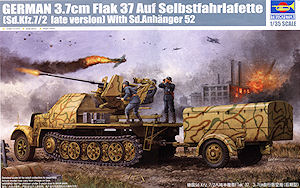
The 3.7cm Flak 37 auf Selbstfahrlafette Sd.Kfz.7/2 followed the 2cm Flakvierling 38 Sd.Kfz.7/1 into production mounting a single Flak36/37/43 depending on the type and was also produced on the standard Sd.Kfz.7 chassis as well as the armoured cab type. The standard trailer used to carry additional ammo was initially the Sd.Ah.52 trailer as well as the Sd.Ah.56 trailer.
Following the actual production Trumpeter have followed the release of their standard Sd.Kfz.7 Mittlere Zugkraftwagen 8t early version (kit #01514) and the Sd.Kfz.7/1 2cm Flakvierling 38 auf Selbstfahrlafette (kit #01523) with this kit of the 3.7cm Flak 37 auf Selbstfahrlafette Sd.Kfz.7/2 Late Type with Sd.Anhanger 52 trailer.
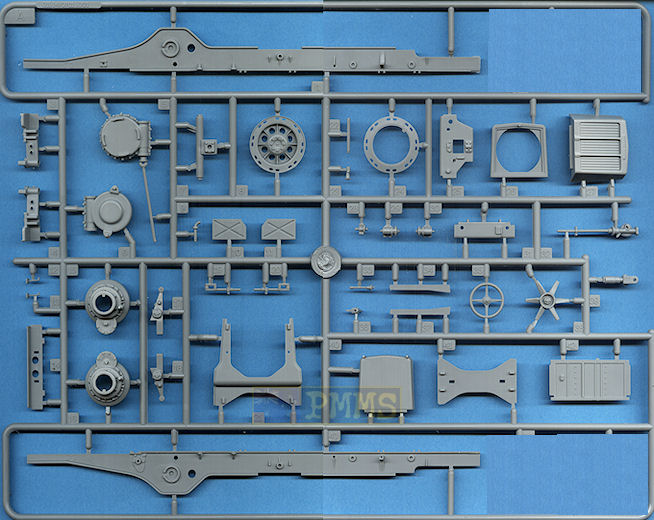
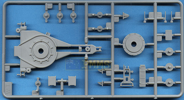
The kit only uses the lower chassis, engine and gearbox from the previous kits with all other parts being new for this kit, most notably there is the late style road wheels, front wheels, tracks and later style instrument panel to allow you to build a proper late Sd.Kfz.7/2.
The kit has 531 parts in the usual Trumpeter light grey plastic, an additional 336 individual track links along 67 etched parts plus the decal sheet and 28 page instruction booklet as well as a colour painting guide sheet.
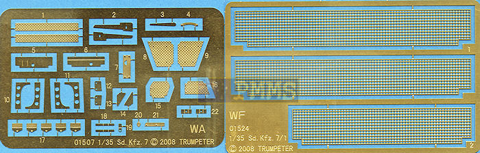
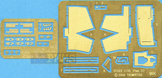
Etched parts
The standard of moulding sees some finely executed detail on the large and small parts with a minimum of pins marks evident and those present are in areas that are unavoidable and fairly easy to deal with.
There is some fine flash on the parts especially the smaller and more intricate parts and a bit of work will be needed to clean this up. Fairly prominent mould seam lines on most parts again require a bit of effort and care is needed not to compromise the detail in the process.
There are numerous small fit issues to contend with on some of the chassis/engine/gearbox parts that sees small adjustments required to get parts to fit and quite a few of the mating surfaces also need to be smoothed out for a more precise fit. The newer parts while still having some minor flash and the mould seam lines to remove appear cleaner overall than the earlier parts.
There is some areas with excellent detail such as the lower chassis assemblies with fully detailed gearbox, engine and large winch as well as the driver’s compartment for very impressive sub-assemblies, it’s a pity much of this is all but hidden after final assembly.
Dimensionally the kit matches available 1:35 plans and data nicely apart from some notable exceptions. The chassis is 3mm too long resulting in the wheel spacings being around 1mm too far apart on the centre sets of road wheels.
Other issues carried over from the initial Sd.Kfz.7 kit is the front fenders being too steeply angled on the inside and the outer curve too shallow. The rivet detail on the front edges of the fenders is from a restored vehicle and not the wartime vehicle and will have to be modified. The drive sprocket teeth are not offset left and right as they should but apart from those issues most other discrepancies are well within acceptable tolerances.
The gearbox is made up of multiple parts with some very well done details enhanced by the addition of 3 etched parts. One of these (part PE-WA21) has to be bent at right angles and this did pose a few problems as the metal is quite thick and it is very difficult to hold the narrow part in an etched bending tool and I had to anneal the part to aid in bending, a lot of work for a small part that is basically hidden from view and you may choose to just forget it.
The side mounted drum brakes do not fit flush to the sides of the gearbox and the fit is rather loose meaning you have to be careful to ensure these line up square with the gearbox and the front cross member (part A7).
The three gear levers have fine mould seam lines to be removed and you should be careful after assembly as they tend to stick up the air just asking to be damaged.
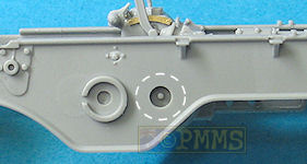
The two full length chassis frames have crisp detail in both sides and no pin marks present but there are substantial mould seams along the top and bottom surfaces to be removed.
There are three small parts added to the sides of the frames and I had to trim the locating pins for a better fit with the assembled gearbox trapped between the two frames, but the fit is very loose and you have to ensued it is aligned perfectly level with the chassis frame, there is a small hole in the chassis that has to line up with the locating pin on the brake drums which you should align by eye.
The cross member for the front suspension spring does not fit well at all and as this has repercussions not only for the sit of the vehicle but the fit of the large front hull/fender assembly and I deviated from the instruction sequences slightly to ensure this was glued in the right place leaving the cross member off at this stage.
The central rear chassis assembly is made up of over a dozen parts and while nicely detailed there is a bit of work involved with some parts needing minor trimming for a better fit and the usual moulding seams and some flash to remove as well as a couple of etched parts for added definition.
To fit the front suspension cross member I temporally added the front hull/fender part WA4 to ensure the cross member is in the right place as the fit is not that good and has a bearing on the alignment of the chassis.
The front suspension spring has the springs in two parts with a quite substantial central join seam to be removed which will take a bit of effort but thankfully the spring detail is free of any pin marks.
The large front suspension arm has separate linkages that allow you to make the wheels steerable and these fit together easily buy I had to open up the pin locating holes a little to allow the retaining pin (part B33) to fit better. This pin is fine plastic so don’t force it into place as it will break and you will have problems from there, a small dab of glue will hold the pin in place but make sure you don’t glue the turning bracket by mistake.
The wheel steering connecting rod fits neatly and is held in place by the rear suspension bracket on the axle so you don’t have to worry about this coming adrift and added to the chassis are the 4 small steering rods from the steering junction box to the front suspension and fitting the 4 small linkages required the enlarging of all locating holes and trimming of the locating pins to get these to fit properly which was a little tedious.
These 4 small brackets are not designed to move and after attaching the steering linkage arm (part D4) this means the front wheels are no longer steerable which sort of defeats the whole steering thing. You can make the 4 small steering linkages and steering arm workable by adding small pins but there is a lot of additional work involved?
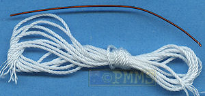
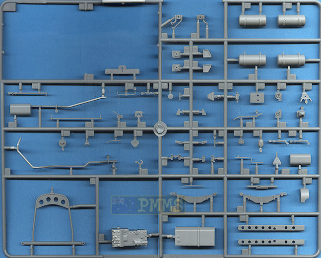
The winch has 4 main parts with 5 additional etched parts and the thread added for the winch cable. The small etched brackets have the cable guide pins added from the copper wire provided and it’s best to solder these as super glue just won’t hold on a join such as this. Just remember to wind on the thread cable before adding the guide pins as it’s a nightmare if the pins are in place. The assembly is added to the 2 etched brackets on the chassis frame with the power take off shaft inserted into the locating hole on the back of the gearbox and there shouldn’t be any problems here.
At the back is the rear chassis bulkhead with separate parts for the large towing pintle, the compressed air outlet and tow cable rollers and guides as well as the large tow cable hook which you would attach to the cable after treading it through the bulkhead from the winch. There is also a small etched bracket with pin made from the wire supplied and the exhaust pipe is also inserted through the hole in bulkhead as you attach this later during construction.
Also added to the chassis are the two part compressed air tanks and the large fuel tank made up of 4 parts and this fits neatly to the supports included on the chassis frames plus a number of smaller brackets and etched parts.
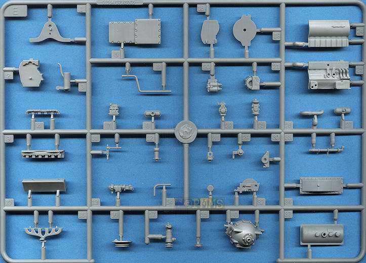
The Maybach HL62TUK engine provided is a highly detailed assembly made up of 37 plastic parts and a couple of etched parts with the assembled engine matching the photos in the WWP Sd.Kfz.7 book very well and includes most if not all of the smaller engine accessory parts.
Detail on the parts is very good but with the usual mould seams to remove as well as some minor flash with the fit fairly good overall but some trimming is needed to get an even fit on some and there are a few traps to look out for.
You should test fit every part before gluing to ensure no trimming is needed and all went fairly smoothly until fitting the top rocker cover with the half moon bracket on top of part E32 requiring trimming in size for this to fit.
At the front is the engine bearing part E1 and it is very important this is fitted perfectly level so the engine will sit properly in the chassis engine mounts but there is nothing to ensure the correct placement of the part and you have to align this by eye which is not the easiest when the engine is separate from the chassis.
I found it easier to leave off part E1 until you have attached the rear bell housing (part E36) which does have precise locating recesses in the engine block and then align the “legs” on part E1 to the mounting pins on part E36.
When fitting the bell housing (part E36) you will need to trim some plastic off part E21 to ensure the bell housing sits flush with the engine block as it will be at an angle if you don’t compromising the fit of the engine to the chassis.
Also the rear fill plate on the bell housing (part E19) does not fit flush inside the housing and you will need to trim this for a better fit which again effects the overall alignment of the engine/chassis fit.
While the engine is quite detailed and complete there are no pulley belts supplied and you should add these from thin paper or tape to finish off the front fan/pulley assembly and there are two radiator pipes added to the engine which mate to locating holes in the radiator when attached and you may want to leave off these pipes until the radiator is added to align these more easily?
The large air cleaner is attached the front body/fender part later in step 19 and this has to mate to the top of the carburettor and depending on the fit of the engine/chassis join some trimming may be needed to fit the air cleaner pipe to the carburettor. The full exhaust pipe and muffler is also added in step 19 and the pipe mates to the exhaust manifold on the left of the engine and again some minor manoeuvring may be needed depending on the fit of other parts.
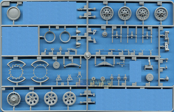
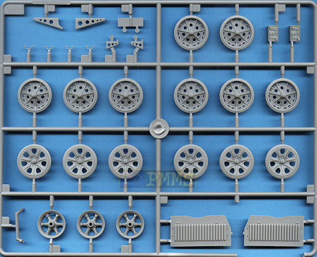
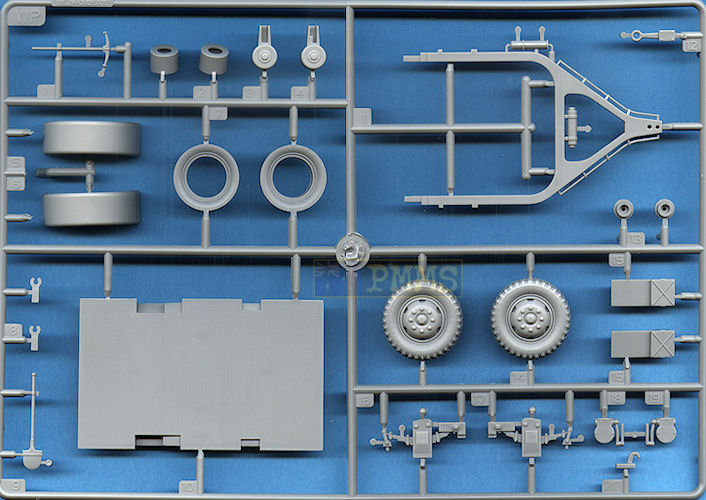
The front wheel hubs are in two halves and feature very well done rim/spoke detail that includes the moulded on valve stem with a separate central hub cap, the wheel also represents the later style with the central hub extending slightly further out than on the earlier wheel. The inside of the cast “star” hub is correctly hollowed out as it should be for a good representation of the front wheel.
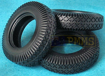
The vinyl tyres are from the Sd.Kfz.7/1 kit and feature the correct WWII tread pattern as well as extended around the shoulder and this fits easily to the wheel hub, the only issue here is the rims stick out a little from the tyre sidewall but there is little you do about this as the vinyl tyres make adjustments difficult.
The outer road wheels are new and feature the late style wheel hubs along with excellent stamped rim detail but there is a little flash in some of the lightening holes which is minor and easily removed.
Note there are different inner wheels for the idlers (parts B25) with longer axle mountings with the outer wheel the same as for the road wheel stations 1, 3 and 5. For stations 2, 4 and 6 you obviously don’t fit the outer wheel until adding the wheels to the axles as they intermesh with the central wheels as is normal for German half-tracks.
The drive sprockets are quite detailed being made up of 5 plastic and 1 etched part each but there a number of issues here unfortunately.
There is considerable flash in the sprocket lightening holes and this will take a bit of effort to remove and the central drive roller ring is in two halves that fit together but for some reason the outer roller detail is only included on the rollers that face the inside when attached with the outer roller being just plain plastic devoid of detail?
When gluing the drive roller discs together you have to ensure they are as tight together as possible as this will affect the fit of the track links later if not a snug fit.
One roller disc has small brackets included that fit into the corresponding recesses in the outer drive sprocket half but note as one of the brackets is half the size of the others and this must be aligned with the grease point on the sprocket to fit correctly. Unfortunately the instructions don’t tell you this and if you try and fit the roller disc any other way it will not fit properly.
The sprockets include the central bolt head detail and the separate covered bracket (part B41) and there is also the circular foot step with tread plate included as an etched part that has the bent to form the circle before adding to the bracket. Annealing this part by running through a candle flame will assist in bending the step and this adds a nice touch to the sprocket hub.
Another issue is the drive rollers are not offset as they should be but are located centrally on the outer sprocket facets which are very noticeable on these larger sprockets and given the way the drive roller discs are attached to the sprockets a bit of work is required to correct this? See Modification guide here.
The drive sprockets on all German half tracks feature “teeth” in the form of small rollers that intermesh with the track links, the drive sprockets themselves have flat facets sections around the sprocket that the track links “sit” flush on as the pass around the sprocket. The rollers are not located centrally on the flat section but offset towards the front of the facets to allow them to mesh with the tracks better and this means the sprockets are not interchangeable between left and right.
There should also be bolt heads around the inner sprockets rims but these are very difficult to include with current moulding technology and you may want to add these for greater detail but with the incorrect drive roller position it may be a wasted effort? Another issue with the sprocket hub is there are 7 engraved segment lines on the sprocket disc face but these should not be there and unfortunately it’s very difficult to fill these given the angles and recessed sprocket face.
There is a bit of flash and the mould seam lines to be removed from the suspension parts but they assemble easily although the locating surface for the rear suspension units (parts S3/A4) need to be trimmed flush but the locating points are quite large making for robust assembles.
I also had to shorten to locating pins on the rear springs (parts B18) to fit the chassis locating holes better and you should ensure the front springs (parts B36) are aligned evenly with the chassis.
There is also substantial mould seams on the idler mountings to be removed and you should not glue the idler mounts in place but leave these free so you can adjust the idler position when fitting the tracks later while adding the twin axle to the bogies is very straightforward without any problems.
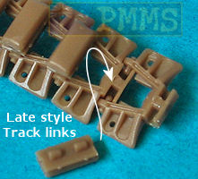
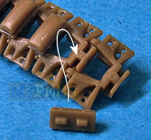
The tracks are individual working links and are the later style with only one hole on each side of each link and different cast detail on the link face. These assemble in what is now standard for this type of track and follows how the real things are joined with each link fitting into the next and held in place with the rubber track pad.
Dimensionally the real track links are 360mm wide equalling 10.3mm in 1:35 scale and the kit links measure 10.3mm to be spot on and the separate track pads are in two parts, the rubber section and lower attachment plate. This take a little longer to assemble the pads before tackling the track links proper but results in very good detail definition on the pads.
There are three small sprue attachment burs to clean from each track link but other than that assembly is straightforward as you simply fit one link into the next and glue the track pad in place, just ensure you don’t use too much glue and they will articulate easily after the glues dries.
Fitting the track to the drive sprockets will depend if you have fixed the roller offset, if not the links do not sit flush to the sprocket facets leaving gaps which is noticeable but if corrected the tracks sit nice and flush around the sprockets.
comparison with the earlier style track to show the different details
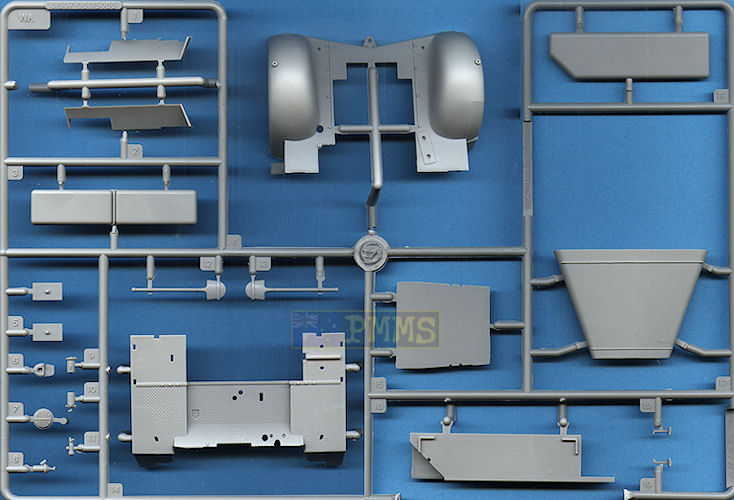
The front fenders are moulded in one piece with the front body and tow hitch included but there are a couple of issues to address with the first being the three large rivets with bolt heads on the lower front edges which are not wartime fittings but were added to the museum vehicle. The bolts have been reduced in size but should still be removed along with the mould seams round them and leave just the flat round rivet heads as seen on wartime half-tracks. There should also be fender brackets on the inside of the fenders which is what the rivets are for if you wish to add this additional detail.
Another issue is the angle on the inside of the fenders is too upright and should be more angled but this is rather subtle from some angles and very difficult to remedy and some may choose to overlook this on the finished model? The height of the fender curve is also too shallow but may not be that noticeable on the finished model, see comparison review of the Sd.Kfz7/1 kits for details.
At the front of the part is the forward tow shackle bracket with what seems like a large mould seam along to top above the tow bracket but this is in fact the metal plate edge on the real vehicle and should remain in place. Added to the tow shackle is the large pin and you could add a bit of fine chain to enhance the detail here a little.
The lip around the bottom of the fenders is a little rough and requires some sanding to smooth out and the heat exchanger pipe is added under the right fender and you just need to drill out the end of the pipe that exits the side lip of the fender to improve the appearance.
The large radiator housing has the front louvers and mesh moulded as one closed unit and not open but we are yet to see this feature rendered correctly in any half-track kit so can’t single this out for any more comment than the others. At the top is the “KRAUSS-MAFFEI” name plate embossed and a separate radiator cap added to the top. But all this detail is hidden when you add the large V shaped armour plate in front of the radiator so isn’t an issue at on this kit.
Inside is the radiator coaming and the radiator housing fits neatly between the fenders without any problems. The side steps are separate parts with etched tread plate panels added as well as other smaller items best left off until later in construction to avoid damage. These include the two large head lights with clear plastic lenses, the two fender mounted width indicator posts which are a little on the thick side and the Notek light with etched mounting as well as a rear view mirror on the left fender.
The two side compartment panels have the closed louvers moulded in place with separate securing T latches and grab handles for a bit of detail definition, these panels fit neatly to the sides of the radiator housing and rear fender floor panel. Added to the side panels is the compartment hood which is cleanly moulded and fits without any problems but you need to open up the holes for the pioneer tools carried on the hood with this vehicle and care is needed to open up the correct holes.
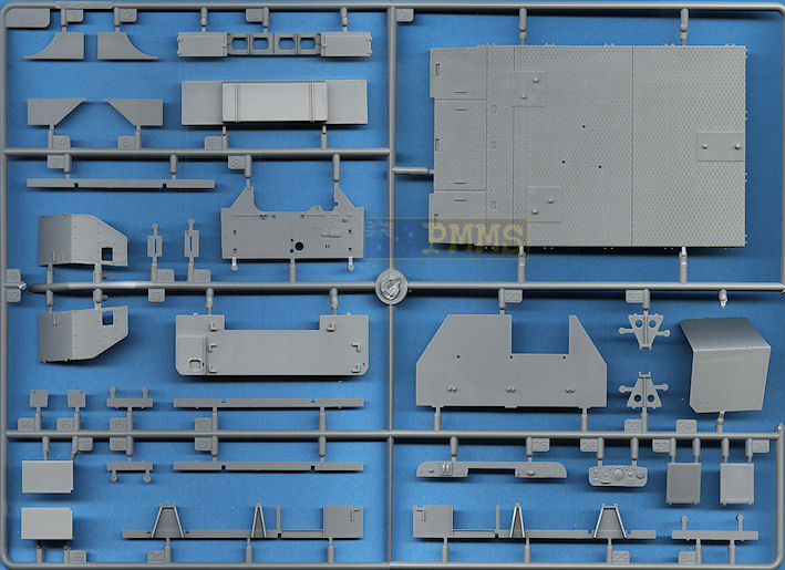
The main engine bulkhead is newly designed for this kit and has detail included on both sides with no pin marks to compromise the detail along with additional perforated braces added on both sides, these needed a little cleanup along the edges and some minor flash from inside the lightening holes. The fit to the bulkhead was good as were the other smaller instrument panel brackets and other items added to the bulkhead as well as the later war round style Bosch horn.
The cabin floor has fine tread plate included with separate small brake, clutch and accelerator pedals plus the steering column with the steering wheel having hand grip detail on the underside and two etched column supports to be added with the column fitting through the recess in the floor for precise location of the lower steering box to the chassis.
To fit the floor you have to feed the three gear shift levers from the gearbox through the floor openings while at the same time manoeuvring around the steering wheel column with the engine bulkhead restricting movement of the floor which is all quite tricky.
The instrument panel is the later or “mid” style for want of a better word as it has additional dials from the earlier design on the separate dial cluster panel with again the dial faces and small data placards provided on the decal sheet. Behind the dial cluster is the additional mounting bracket and a small etched bracket that needs care when bending to shape.
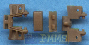
The crew seat has the lower bulkhead that has the two shovel brackets from the prime mover and these should be removed and this includes the new square profile fenders.
The seat cushions have been revised and are now smooth without the heavy texturing of the earlier kits but the lower seat should be in two segments, the driver’s seat and ¾ length passenger seats not the full width seat as provided and a bit of work will be needed to remedy this.
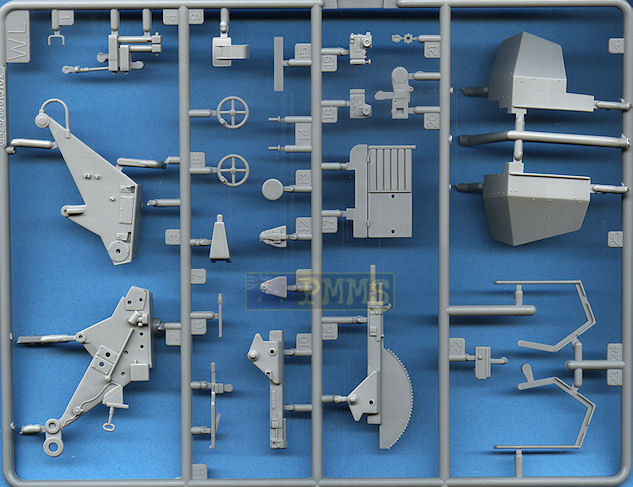
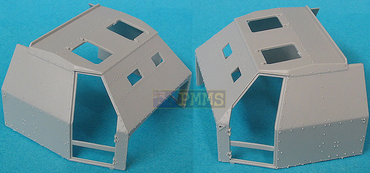
Probably the most prominent feature of this kit apart from the 3.7cm Flak gun is the large armoured cab and this is provided as a single large moulding with separate side entry doors and top hatches.
There are two different style of armoured cab fitted to these vehicles, one with two bolted panels on the sides and doors and one with single piece curved side panels without the middle row of bolts used on the bolted version.
Unfortunately Trumpeter have mixed the two types with the curved profile panels but also the middle row of bolts from the bolted version and you will need to carefully remove the two rows of bolts at the curve line with a sharp #11 blade. See the detail images for a guide on the bolt heads to be removed.
The fit of the armoured cab to the lower floor and engine bulkhead is very good not requiring any trimming on my kit. I also found it easier to fit the engine bulkhead to the cab before fitting to the lower floor as opposed to fitting the bulkhead to the lower chassis first as per the instructions.
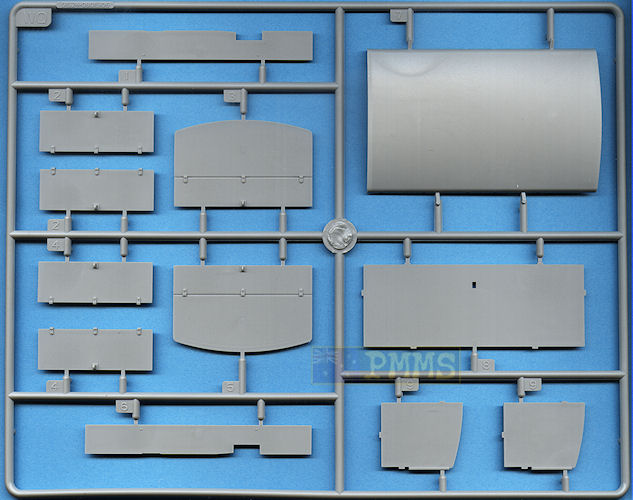
The large rear bed moulding has nice tread plate texture included with additional mounting brackets added to the undersides along with the spare wheel.
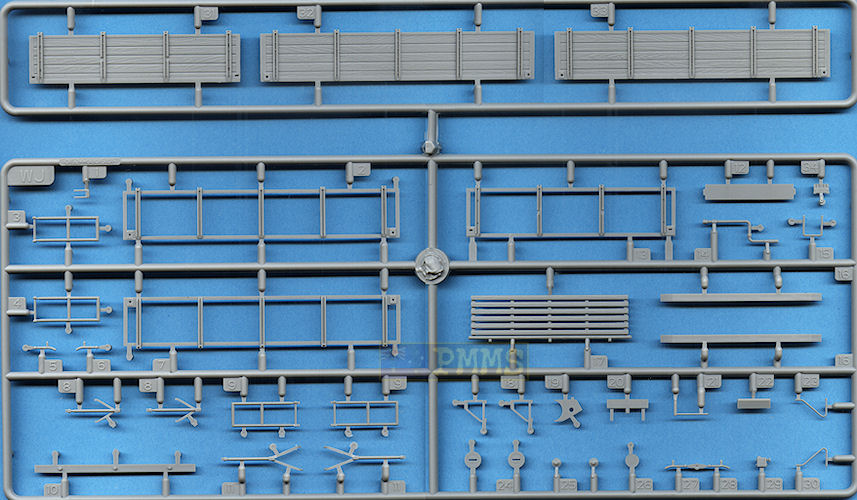
There are two types of fold down sides provided for the rear bed, one has the plastic frames with etched brass mesh but these don’t really represent the slatted style of the actual steel mesh. They do have the horizontal slats double etched and the vertical slats recessed and this gives a better impression than on other attempts to represent the proper slatted side mesh of the Sd.Kfz.7/1-2.
The other is the later wooden plank sides and these feature very nicely done wood grain texturing that has different grain pattern on each plank section that gives a good representation of the wood grain.
The rear panel has finely moulded folding steps that again requires care removing from the sprues and these can be positioned raised or lowered depending on the position of the mesh panel. Also added to the side mesh panels are the pioneer tools that have their attachment clips and brackets moulded on and again these will probable be provided in the etched update sets to come.
At the front of the bed is a fold down wooden crew seat that again has nice wood grain effect but missing altogether are the six racks for the crew Kar98 rifles usually fitted to the rear of the cab bulkhead and these will have to be found elsewhere.
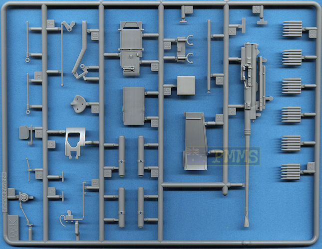
This gun is all new for the kit and is nicely done overall with most of the major features of the gun mounting included although there is scope for additional detail to improve the final appearance.
There are a few pin marks on some of the gun parts but most of these are hidden after assembly so you may want to check before filling the holes to save a bit of work.
The 3.7cm gun itself matches available plans in size and barrel length apart from the flash suppressor which is only about 2/3rds the size it should be, this making the overall length a little short. Detail on the flash suppressor is also basic with none of the neck or cone holes fully opened out and the better option is to replace the barrel with any of the available 3.7cm Flak37 metal barrels. For this exercise I have used the new Adlers Nest metal barrel in the anodised finish (set #ANM-35030B) as this has the correct sized flash suppressor with very thin cone and fully opened up neck and cone holes.
The main gun cradle is in two halves and you will need to remove the mould seam from the edges but other than that there is no other cleanup needed and this has additional parts added on the insides with the cradle trapping the assembled gun between them to allow full elevation. The two recuperator cylinders are in two halves each resulting in a small join seam to be eliminated and the separate piston rod fits neatly into the cylinders allowing these to extend and retract as the gun is elevated providing you are careful with the glue when attaching the pistons to the cradle.
Additional details added to the cradle are the gunner’s controls with two hand wheels, three part gunner’s seat and foot rest/firing pedals (as an etched part) as well as a three part a Flakvisier 40 sight. This represents the Flakvisier 40 details quite well but it lacks the eye guard or the additional telescopic sight used for sighting ground targets.
The gunner’s armoured shield and small front gun shield are provided in plastic or as etched parts for a nice choice depending on your preference. The plastic shields are a little on the thick side with bevelled edges to give a better impression but the etched shields provide are far better representation of the actual shields.
There is no assembly of the plastic shields other that fitting to the gun cradle while the etched gunners shield has to be bent to shape and the small side fillet soldered or super glued into position with soldering the preferred method for a stronger join.
On the left side is the ammo feed slide for two 6 round clips provided as well as the loader’s platform with and another 4 clips stowed on the platform plus the mounting brackets for the main gun shields. Not all guns had the main shields fitted and if not using the shields the mounting brackets would be omitted.
The main gun shields are again provided in plastic or etched metal with the etched shields representing the actual 8mm shields far better than the thicker plastic shields. The etched shields have to be bent to shape using the angles of the plastic shields as a guide and again soldering the joins results in a stronger join. The assembled shields fit to the plastic mounting brackets in the same manner as the plastic shields.
The tricycle base has nice details with a separate workable travel lock and also separate round “feet” for fitting the base to the rear tray bed. Reference photos show both these round “feet” or three small triangular brackets welded to the tray bed. These triangular brackets are actually provided in the kit but not mentioned in the instructions should you wish to add these? The kit is designed to use the round mounting “feet” with square plates with locating pins on the tray bed and would be the easiest configuration which is supported by photo references.
As with the Sd.Kfz.7/1 kit you also get the ammo trailer usually towed to provide additional ammo and for this kit you get the larger Sd.Ah.52 Trailer, references indicate this was used as well as the larger Sd.Ah.56/57 Trailer with quite a few photos available showing both in use.
Unfortunately Trumpeter has again mixed up the details between the Sd.Ah.52 and Sd.Ah.56 trailer with the trailer chassis/frame being that of the Sd.Ah.52 while the trailer box and wheels is that of the late model Sd.Ah.56 trailer. It should also be noted the early Sd.Ah.56 trailer had a flat top while the later type had a rounded top as included in the kit.
This combination results in the trailer box being off centre with the rear overhang being too great resulting in the centre of gravity being out of position.
The large trailer frame is the same as used for the towed 3.7cm Flak36/37 with the ammo storage box added and the U shaped frame is moulded in one piece including the forward triangular bracket. There is a large mould seam around the frame that will need to be eliminated with this being the only cleanup needed and added to the frame are the suspension springs, wheel fenders with additional etched brackets and the two rear mounting assemblies. The main wheels have the tyre and rim in one piece with a small rear insert and axle stub designed to allow the wheels to rotate after fitting to the axles.
Assembly here was straightforward with good part fit not requiring any trimming or filling making for a quick and easy job.
The large ammo box has the floor section to which is added three internal bulkheads that ensure the remaining side panels are all located precisely and perfectly square and again the fit of the side panels and roof was spot on resulting in a perfectly square box with not gaps or other trimming/filling required.
There are additional small etched latches added to the side doors and while the etched parts don’t have any bending lines they are quite thin and easily bent to conform to the latches without any great problems. The fully assembled ammo box also fits perfectly to the lower frame and actually holds in place without glue should you want to separate these at some stage for a diorama setting.
These are the usual exploded view drawings which in most cases are easy to follow and there shouldn’t be any problems?
You should study the sequences carefully and test fit the parts before gluing given the number of parts requiring some form of trimming to get a good fit as mentioned above.
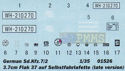
The decal sheet is well printed with good colour register and has number plates and unit markings for 1 Wehrmacht vehicle although 2 colour schemes are shown on the full colour painting guide included in the kit along with the instrument dials and data placards mentioned earlier.
The colour painting guide has 5 view illustrations of two vehicles with the alternate decal options shown so you can basically make up your own paint finish if no references are available?
While this kit carries over some accuracy issues such as the drive sprocket roller offset, the chassis length and fender profile it also includes excellent details in the engine/gearbox assemblies as the full compliment of driver’s pedals and decals for the instrument panel.
But what makes this kit very attractive is the inclusion of the later style road wheels, front wheel hubs, the later style track links and the ”mid” style instrument and Trumpeter are to be complimented for adding the late features and not just re-boxing the previous early wheels/tracks and a calling it “late” production.
The new 3.7 Flak 37 mounting again has some nice features such as the etched gun shields with the level of detail adequate for most but could be enhanced with additional detailing.
The mix-up of trailer features is unfortunate and detracts a little from the overall appeal but the kit still has many pluses to offset some of the minuses.
Employing good old fashioned modelling skills will result in an impressive kit and as mentioned the inclusion of the truly late features is a big bonus
Highly Recommended. (just)

Detail Images
Close new window to return to review
| Sd.Kfz.7 - 8 ton Zugkraftwagen Krauss-Maffei and variants Nuts & Bolts Volume 34 Dr. Nicolaus Hettler  |
Halbketten Zugkraftwagen 8t Sd.Kfz.7/1/2 AFV Super Detail Photo Vol.9 Published by Model Art Co.Ltd.  |
Flak Auf Sd.Kfz.7 Part 1 Kagero Photosniper No.9 ISBN: 83-914824-3-X  |
| Flak Selbstfahrlafetten and Flakpanzer Panzer Tracts No.12 Doyle/Jentz  |
Sd.Kfz.7 in detail Special Museum Line No.36 Wings & Wheels Publications ISBN 80-86416-60-7  |
Flak
at War Trojca Publications Waldemar Trojca, Karlheinz Münch ISBN: 83-60041-15-6  |
| Allied & Axis
No.21 Ampersand Publishing Sd.Kfz.7, 8-ton KM m 11 halftrack  |
German Anti-Aircraft Combat Vehicles Revised Edition Ground Power Special Feb '08  |
Ground Power Magazine #66 - 11/1999 GALILEO Publishing Co.,Ltd. Japan  |
 for
the review kit.
for
the review kit.